CN-Series
Deploy the Kubernetes CNF L3 in Standalone Mode
Table of Contents
Deploy the Kubernetes CNF L3 in Standalone Mode
| Where Can I Use This? | What Do I Need? |
|---|---|
|
|
You can deploy the CN-Series Firewall as a
Container Network Function (CNF) in L3 Standalone mode in your Kubernetes
environment.
The CN-Series now supports the traffic through
a vRouter, where static routes are configured to redirect traffic
to the dataplane interfaces of the firewall. For reverse direction,
the traffic is redirected to the same firewall using L3 Policy Based
Routing (PBR) with IPv4 IP addresses. IP addresses of the interfaces in
K8s environment are typically programmed through the CNI using DHCP.
To
deploy the Kubernetes CNF in L3 standalone mode:
- Set up your Kubernetes cluster.To create a cluster in AWS EKS, do the following:
- Click the Services navigation menu, go to Containers->Elastic Kubernetes Service.
![]()
- Click Create Cluster.
- Fill in the required details, and then click Create.
![]()
- Verify that the cluster has adequate resources. Make sure that cluster has the CN-Series Prerequisites resources to support the firewall:kubectl get nodeskubectl describe node <node-name>View the information under the Capacity heading in the command output to see the CPU and memory available on the specified node.The CPU, memory and disk storage allocation will depend on your needs. See CN-Series Performance and ScalingEnsure that you have the following information:
- Collect the Endpoint IP address for setting up the API server on Panorama. Panorama uses this IP address to connect to your Kubernetes cluster.
- Collect the template stack name, device group name, Panorama IP address, and optionally the Log Collector Group Name from Panorama.
- Collect the authorization code and auto-registration PIN ID and value.
- The location of the container image repository to which you downloaded the images.
Create a cert secret. (optional) If you configured a custom certificate in the Kubernetes plugin for Panorama, you must create the cert secret by executing the following command. Do not change the file name from ca.crt. The volume for custom certificates in pan-cn-mgmt-0.yaml and pan-cn-ngfw-0.yaml is optional.kubectl -n kube-system create secret generic custom-ca --from-file=ca.crtEdit the YAML files to provide the details required to deploy the CN-Series firewalls.- pan-cn-mgmt-0.yaml
- pan-cn-mgmt-configmap-0.yaml
- pan-cn-ngfw-configmap-0.yaml
You should replace the image path in the YAML files to include the path to your private registry and provide the required parameters. See Editable Parameters in CN-Series Deployment YAML Files for details.The following default values are defined in the pan-cn-mgmt-configmap-0.yaml file.pan-cn-mgmt-configmap-0.yaml:metadata:name: pan-mgmt-confignamespace: kube-systemdatadata:PAN_SERVICE_NAME: pan-mgmt-svc-0PAN_MGMT_SECRET: pan-mgmt-secretYou can add the numa option for CPU pinning. Add the single numa node number for PAN_NUMA_ENABLED parameter in the pan-cn-ngfw-configmap-0.yaml file.To successfully deploy the CN-Series-as-a-kubernetes-CNF with layer 3 support:- Each Kubernetes node should have at least three interfaces: Management (default), HA2 link, and data interface.
- For CN-Series firewall in L3 mode, there should be at least two interfaces: Management (default), and data interface.
- Modify the new Network Attachment definition YAML files with the following changes:
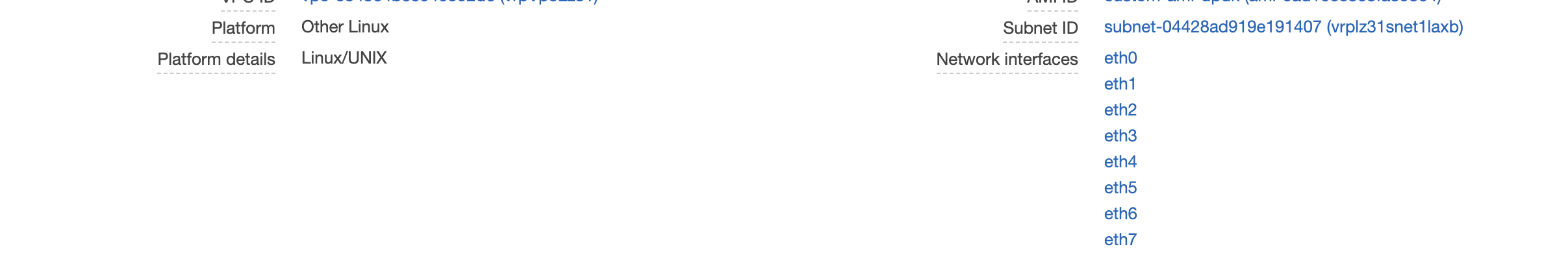
- On the workernode, retrieve the pciBusID value from the hypervisor interface by running the following command:lspci | grep -i etherFor example:00:05.0 Ethernet controller: Amazon.com, Inc. Elastic Network Adapter (ENA)00:06.0 Ethernet controller: Amazon.com, Inc. Elastic Network Adapter (ENA)00:07.0 Ethernet controller: Amazon.com, Inc. Elastic Network Adapter (ENA)00:08.0 Ethernet controller: Amazon.com, Inc. Elastic Network Adapter (ENA)00:09.0 Ethernet controller: Amazon.com, Inc. Elastic Network Adapter (ENA)00:0a.0 Ethernet controller: Amazon.com, Inc. Elastic Network Adapter (ENA)00:0b.0 Ethernet controller: Amazon.com, Inc. Elastic Network Adapter (ENA)00:0c.0 Ethernet controller: Amazon.com, Inc. Elastic Network Adapter (ENA)The PCI ordering is same as ordering of the eth interfaces as shown on AWS EC2 UI
![]() Add the above retrieved pciBusID value to the following Network definition files:net-attach-def-1.yamlnet-attach-def-2.yamlnet-attach-def-3.yamlDeploy the CN-MGMT StatefulSet.By default, the management plane is deployed as a StatefulSet that provides fault tolerance. Only one firewall CN-NGFW pod can connect to a CN-MGMT StatefulSet.
Add the above retrieved pciBusID value to the following Network definition files:net-attach-def-1.yamlnet-attach-def-2.yamlnet-attach-def-3.yamlDeploy the CN-MGMT StatefulSet.By default, the management plane is deployed as a StatefulSet that provides fault tolerance. Only one firewall CN-NGFW pod can connect to a CN-MGMT StatefulSet.- (Required for statically provisioned PVs only) Deploy the Persistent Volumes (PVs) for the CN-MGMT StatefulSet.
- Create the directories to match the local volume names defined in the pan-cn-pv-local.yaml.You need six (6) directories on at least 2 worker nodes. Log in to each worker node on which the CN-MGMT StatefulSet will be deployed to create the directories. For example, to create directories named /mnt/pan-local1 to /mnt/pan-local6, use the command:
mkdir -p /mnt/pan-local1 /mnt/pan-local2 /mnt/pan-local3 /mnt/pan-local4 /mnt/pan-local5 /mnt/pan-local6
- Modify pan-cn-pv-local.yaml.Match the hostname under nodeaffinity, and verify that you have modified the directories you created above in spec.local.path then deploy the file to create a new storageclass pan-local-storage and local PVs.
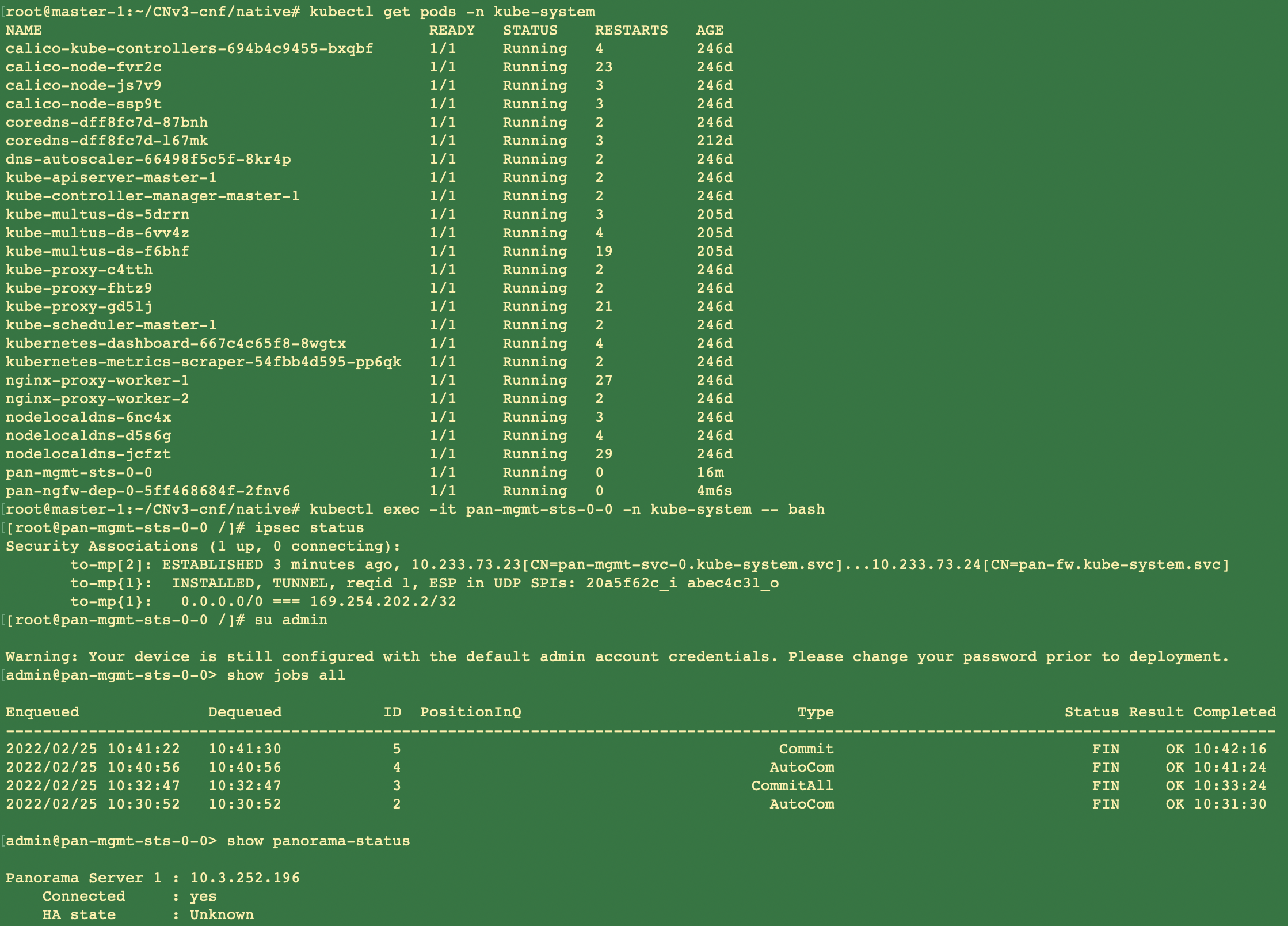
Verify that you have modified the pan-cn-mgmt-configmap and pan-cn-mgmt YAML files.Use Kubectl to run the yaml files.kubectl apply -f pan-cn-mgmt-secret.yamlkubectl apply -f pan-cn-mgmt-configmap-0.yamlkubectl apply -f $dir/pan-cn-mgmt-0.yamlkubectl apply -f $dir/net-attach-def-1.yamlkubectl apply -f $dir/net-attach-def-2.yamlkubectl apply -f $dir/pan-cn-mgmt-0.yamlkubectl apply -f $dir/pan-cn-ngfw-configmap-0.yamlkubectl apply -f $dir/pan-cn-ngfw-0.yamlYou must run the pan-mgmt-serviceaccount.yaml, only if you had not previously completed the Create Service Accounts for Cluster Authentication.Verify that the CN-MGMT pods are up.It takes about 5-6 minutes.Use kubectl get pods -l app=pan-mgmt -n kube-systemNAME READY STATUS RESTARTS AGEpan-mgmt-sts-0 1/1 Running 0 27hpan-mgmt-sts-1 1/1 Running 0 27hDeploy the CN-NGFW in k8s-CNF mode.- Verify that you have modified the YAML files as detailed in Step 3.containers: - name: pan-ngfw-container image: <your-private-registry-image-path>You should ensure that the multus daemonset is installed and the network attachment definition files are created. The parameter value for PAN_SERVICE_NAME in pan-cn-ngfw-configmap-0.yaml file should match the Service Name parameter value in pan-cn-mgmt-0.yaml file.For data interfaces for CN-NFGW pods, the CNIs and interface resources should be added to CN-NFGW YAML files as required. For example:k8s.v1.cni.cncf.io/networks: <interface-cni1>@eth1,<interface-cni2>@eth2To enable the DPDK support, you should ensure that the PAN_DATA_MODE parameter value is dpdk in pan-cn-ngfw-configmap-0.yaml file.Also, the HUGEPAGE_MEMORY_REQUEST parameter value should match the hugepage memory request in pan-cn-ngfw-0.yaml file.For more information, see Configure DPDK on CN-Series Firewall.Use Kubectl apply to run the pan-cn-ngfw-configmap-0.yaml.kubectl apply -f pan-cn-ngfw-configmap-0.yamlUse Kubectl apply to run the pan-cn-ngfw-0.yaml and pan-cn-ngfw-1.yaml.kubectl apply -f pan-cn-ngfw-0.yamlVerify that the CN-NGFW Pods are running.kubectl get pods -n kube-system -l app=pan-ngfw -o wideDeploy the CN-NGFW pods. Do the following:
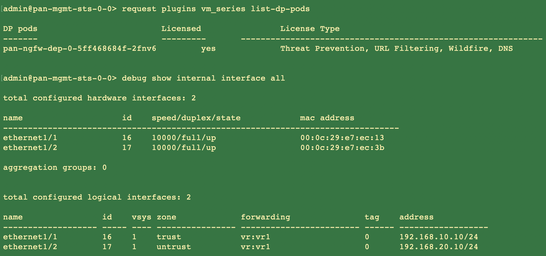
- Verify that you have modified the YAML files as detailed in PAN-CN-NGFW-CONFIGMAP-0 and PAN-CN-NGFW-0.containers: - name: pan-ngfw-container image: <your-private-registry-image-path>Use Kubectl apply to run the pan-cn-ngfw-configmap.yaml.kubectl apply -f pan-cn-ngfw-configmap.yamlUse Kubectl apply to run the pan-cn-ngfw.yaml.kubectl apply -f pan-cn-ngfw.yamlVerify that the CN-NGFW Pods are running.kubectl get pods -n kube-system -l app=pan-ngfw -o wideVerify that you can see CN-MGMT and CN-NGFW on the Kubernetes cluster. Run the following command:kubectl -n kube-system get pods
![]()
![]()