Configure the Panorama Plugin for Cisco TrustSec
Table of Contents
Configure the Panorama Plugin for Cisco TrustSec
After you install the plugin, you must also
assign a notify group to your Cisco TrustSec plugin configuration.
A notify group is a list of device groups that includes the firewalls
to which Panorama should push all the tags it retrieves from the
pxGrid server.
Each Panorama with the Cisco TrustSec plugin
installed can support up to 16 pxGrid servers and 16 monitoring
definitions. And each monitoring definition has one pxGrid server
and one notify group.
The Panorama plugin for Cisco
TrustSec currently supports dynamic objects but not static objects.
- (Optional) Bypass proxy server settings, configured on Panorama under , for communication between Panorama and Cisco TrustSec. This command allows Panorama to communicate directly with Cisco TrustSec by bypassing the Panorama proxy configuration while maintaining proxied communication for other services.
- Log in to the Panorama CLI.Execute the following command to enable or disable proxy bypass.admin@Panorama> set plugins cisco_trustsec bypass-proxy {yes|no}Select yes to enable proxy bypass and no to disable proxy bypass. This is set to no by default.Configure the full-sync interval if you want to change it from the default 600 seconds (10 minutes).
- Log in to the Panorama CLI.Enter configure mode.admin@Panorama> configureUse the following command to set the full-sync interval. The range is 600 seconds to 86,400 seconds (one day).admin@Panorama# set plugins cisco_trustsec full-sync-interval <interval-in-seconds>Log in to the Panorama web interface.You must add the firewalls as managed devices on Panorama and create Device Groups so that you can configure Panorama to notify these groups with the VM information it retrieves. Device groups can include VM-Series firewalls or virtual systems on the hardware firewalls.Configure Cisco TrustSec monitoring.
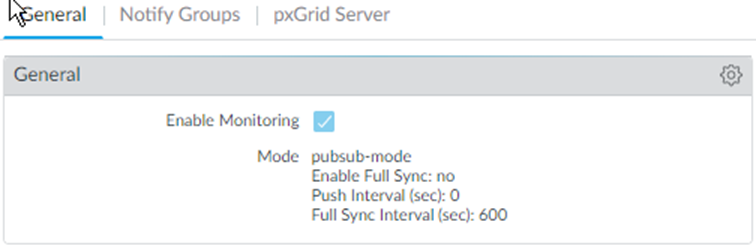
- Select .Enable Cisco TrustSec Monitoring is enabled by default. This enables monitoring for all clusters in your deployment.The user interface selects the PubSub monitoring mode if the Panorama plugin for Cisco TrustSec is 1.0.2 or later is installed on Panorama 10.0.0 or later:
![]() The plugin selects Bulk Sync mode when it is installed on a Panorama version earlier than 10.0.0:
The plugin selects Bulk Sync mode when it is installed on a Panorama version earlier than 10.0.0:![]() Click the gear to edit the setup parameters.
Click the gear to edit the setup parameters.- Push Interval (PubSub only)—Minimum 0, maximum 60 seconds, default is 0 (100 milliseconds).
- Enable Full Sync (PubSub only, optional)—Select this optional to enable a full sync. Default is no.
- Full Sync Interval.
- PubSub—If Enable Full Sync is selected, you can set the full sync interval in seconds. Range is 600 seconds to 86400 seconds (one day), and the default value is 600
- Bulk Sync—Enabled by default in Bulk Sync mode. Range is 600 seconds to 86400 seconds (one day), and the default value is 600.
- Monitoring Interval (Bulk Sync only)—10 to 86400 seconds, default is 60—Set the polling interval at which Panorama queries the pxGrid server for endpoint address information. This is the time period between the end of a monitoring event and the start of the next event.
Create a notify group.- Select .Click Add.Enter a descriptive Name for your notify group.Select the device groups you created in previously.
![]() (Optional) If enabling server identity verification of the pxGrid server, configure a certificate profile on Panorama.Create, activate, and approve the pxGrid client name and client password.
(Optional) If enabling server identity verification of the pxGrid server, configure a certificate profile on Panorama.Create, activate, and approve the pxGrid client name and client password.- Log in to the Panorama CLI.Execute the following command to create the client name.
- If you have a certificate profile, create the client name as follows:admin@Panorama> request plugins cisco_trustsec create-account client-name <client-name> host <ise-server-ip>
- If you skipped Step 6 and you do not have a certificate, enter:request plugins cisco_trustsec create-account server-cert-verification-enabled no client-name <client-name>host <host-name>
Execute the following command to create the client name.admin@Panorama> request plugins cisco_trustsec create-account client-name test host 10.10.10.15 AccountCreate in progress... AccountCreate successful. client nodename: test client password: <xxxxxxxx> AccountActivate in progress... AccountActivate successful. Please approve the account on the server.
Log in to your Cisco ISE server to approve the account.Select .Select the client name you create on Panorama.Click Approve.![]() Add pxGrid server information. The Panorama plugin for Cisco TrustSec supports up to 16 pxGrid (Cisco ISE) servers.
Add pxGrid server information. The Panorama plugin for Cisco TrustSec supports up to 16 pxGrid (Cisco ISE) servers.- Select .Enter a descriptive Name for your pxGrid server.In the Host field, enter the IP address or FQDN for your pxGrid server.Enter the client name you created in the previous step.Enter and confirm the client password you generated in the previous step.Verify the pxGrid server identity.
- Select Verify server certificate.
- Select your certificate profile from the Cert Profile drop-down.
Click OK.![]() Configure the Monitoring Definition.
Configure the Monitoring Definition.- Select and click Add.Enter a descriptive Name and optionally a Description to identify the monitoring definition.Select the pxGrid Server.(Optional) Set Panorama to Monitor pxGrid sessions in AUTHENTICATED state. By default, Panorama retrieves IP-Tag mappings from sessions in the “STARTED” state. ISE sessions have the “STARTED” state when there is a corresponding accounting start packet. If no accounting start packet is present for the session, then the session state is “AUTHENTICATED”.Select the Notify Group.Click OK.
![]() Commit your changes.Create active ISE sessions so that Panorama can learn SGT tags for dynamic address group definition. To create active sessions, use ISE to authenticate devices.Panorama does not collect default SGT tags on ISE.Create dynamic address groups and verify that addresses are added to dynamic address groups.
Commit your changes.Create active ISE sessions so that Panorama can learn SGT tags for dynamic address group definition. To create active sessions, use ISE to authenticate devices.Panorama does not collect default SGT tags on ISE.Create dynamic address groups and verify that addresses are added to dynamic address groups.- Select .Select the Device Group you created for monitoring endpoints in your Cisco TrustSec environment from the Device Group drop-down.Click Add and enter a Name and Description for the dynamic address group.The dynamic address group naming convention is: cts.svr_<server-name>.sgt_<SGT-name>Select Type as Dynamic.Click Add Match Criteria.Select the And or Or operator and click the plus (+) icon next to the security group name to add it to the dynamic address group.Panorama can only display security group tags it has learned from active sessions. Security group tags in live sessions appear in the match criteria list.Select .Click More in the Addresses column of a dynamic address group.Panorama displays a list of IP addresses added to that dynamic address groups based on the match criteria you specified.
![]() Use dynamic address groups in policy.Dynamic address groups are empty until you attach them to a policy. You won’t see any IP addresses in your dynamic address group unless a policy is using it.
Use dynamic address groups in policy.Dynamic address groups are empty until you attach them to a policy. You won’t see any IP addresses in your dynamic address group unless a policy is using it.- Select .Click Add and enter a Name and a Description for the policy.Add the Source Zone to specify the zone from which the traffic originates.Add the Destination Zone at which the traffic is terminating.For the Destination Address, select the dynamic address group you just created.Specify the action— Allow or Deny—for the traffic, and optionally attach the default security profiles to the rule.Repeats Steps 1 through 6 to create another policy rule.Click Commit.(Optional) Update the dynamic objects from the pxGrid server at any time by synchronizing dynamic objects. Synchronizing dynamic objects enables you to maintain context on changes in the virtual environment and allows you to enable applications by automatically updating the dynamic address groups used in policy rules.
- Select .Click Synchronize Dynamic Objects.
![]()