ION 1200 Front Panel
Table of Contents
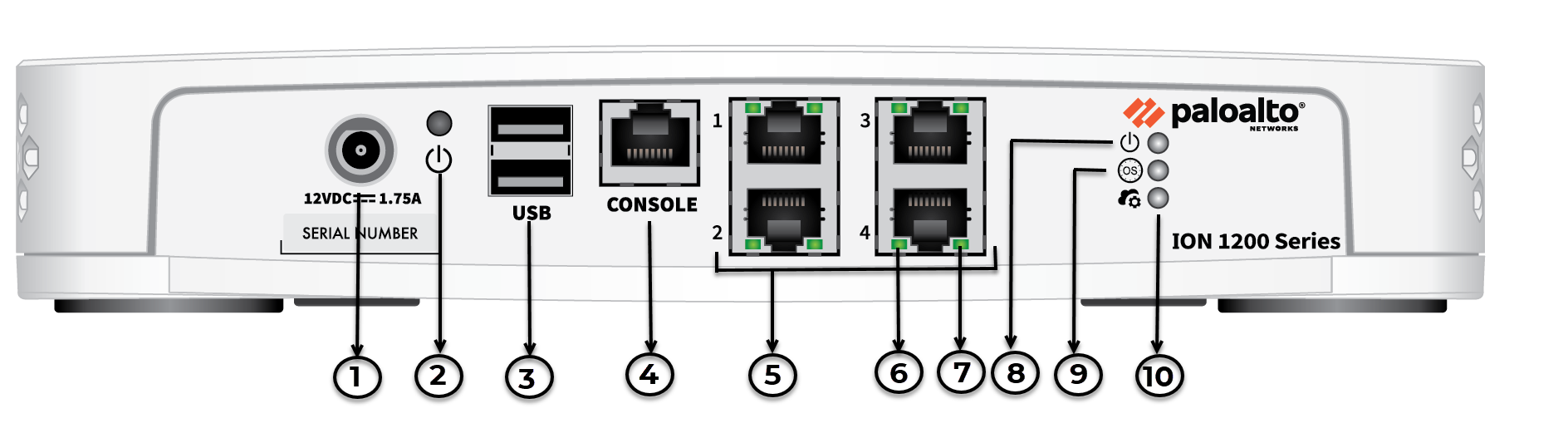
ION 1200 Front Panel
The following image shows the front panel
of the ION 1200 and the table describes the front panel components.
| Item | Component | Description |
|---|---|---|
| 1 | Power | Power input. |
| 2 | Restart Button | Restart button. |
| 3 | USB Port | USB 3.0 (reserved for future use). |
| 4 | Console Port | RJ-45 Serial console port. |
| 5 | Ethernet Ports | RJ-45 WAN/LAN ports. |
| 6 | Link Speed LED | On ethernet ports 1-4, the left LED indicates the link speed. |
| 7 | Activity LED | On ethernet ports 1-4, the right LED indicates the activity on the port. |
| 8 | Power LED | Power LED; the LED turns green when powered on. |
| 9 | OS LED | Operating System status LED. |
| 10 | Controller LED | Controller LED; the LED turns green on successful connection with the Prisma SD-WAN controller. |