Next-Generation Firewall
Strata Cloud Manager
Table of Contents
Strata Cloud Manager
Use Strata Cloud Manager to create a GRE tunnel.
Create a GRE
tunnel to connect two endpoints in a point-to-point logical link.
- Select .For Configuration Scope, select Folders and then select All Firewalls, a specific folder, or the specific firewalls you want to configure. (Don’t choose Global.)Create a tunnel interface.
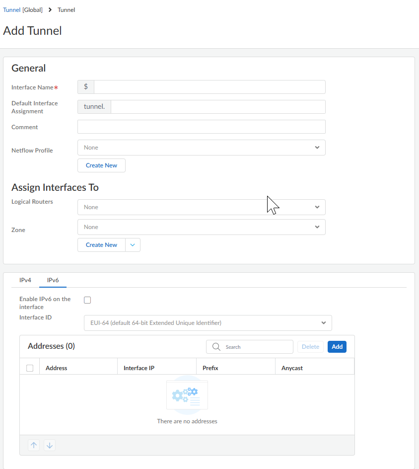
- Select and Add Tunnel.Enter the tunnel Interface Name followed by a period and a number (the range is 1 to 9,999). For example, tunnel.1. (The Default Interface Assignment is tunnel.)(Optional) Enter a Comment about the tunnel interface.(Optional) Select a NetFlow Profile to export statistics about the IP traffic ingressing its interfaces or Create New NetFlow Profile.Assign the interface to a Logical Router or a Virtual Router.Assign the tunnel interface to a security Zone or Create New zone.
![]() Assign an IP address to the tunnel interface. (You must assign an IP address if you want to route to this tunnel or monitor the tunnel endpoint.) The tunnel interface can have IPv4 and IPv6 addresses. You can select IPv4 and Static address type. Select the + and enter one or more IPv4 addresses for the tunnel interface.You can also select IPv6 and Enable IPv6 on the interface.(IPv6 address only) Select EUI-64 (default 64-bit Extended Unique Identifier) or enter the 64-bit extended unique identifier (EUI-64) in hexadecimal format (for example, 00:26:08:FF:FE:DE:4E:29). If you leave this field blank, the firewall uses the EUI-64 generated from the MAC address of the physical interface. If you enable the Use interface ID as host portion option when adding an address, the firewall uses the Interface ID as the host portion of that address.(IPv6 address only) Add one or more IPv6 addresses for the tunnel interface.
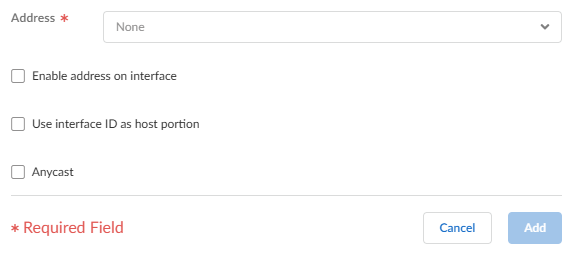
Assign an IP address to the tunnel interface. (You must assign an IP address if you want to route to this tunnel or monitor the tunnel endpoint.) The tunnel interface can have IPv4 and IPv6 addresses. You can select IPv4 and Static address type. Select the + and enter one or more IPv4 addresses for the tunnel interface.You can also select IPv6 and Enable IPv6 on the interface.(IPv6 address only) Select EUI-64 (default 64-bit Extended Unique Identifier) or enter the 64-bit extended unique identifier (EUI-64) in hexadecimal format (for example, 00:26:08:FF:FE:DE:4E:29). If you leave this field blank, the firewall uses the EUI-64 generated from the MAC address of the physical interface. If you enable the Use interface ID as host portion option when adding an address, the firewall uses the Interface ID as the host portion of that address.(IPv6 address only) Add one or more IPv6 addresses for the tunnel interface.![]() (IPv6 address only) Select Enable address in interface to enable that IPv6 address on the interface.(IPv6 address only) Select Anycast to make the IPv6 address (route) an Anycast address (route). This means multiple locations can advertise the same prefix, and IPv6 sends the anycast traffic to the node it considers the nearest, based on routing protocol costs and other factors.(IPv6 address only) Add the IPv6 address to the tunnel interface.Enter the Maximum Transmission Unit (MTU) to specify the largest size of a data packet (in bytes) that the firewall can transmit over the GRE tunnel; the range is 576 to 9,216 in jumbo frame mode; up to 1,500 otherwise.Save the tunnel interface.Create a GRE tunnel to force packets to traverse a specific point-to-point path.
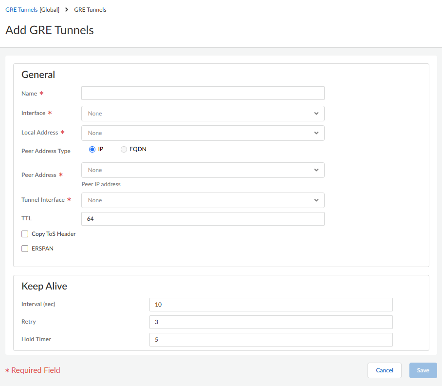
(IPv6 address only) Select Enable address in interface to enable that IPv6 address on the interface.(IPv6 address only) Select Anycast to make the IPv6 address (route) an Anycast address (route). This means multiple locations can advertise the same prefix, and IPv6 sends the anycast traffic to the node it considers the nearest, based on routing protocol costs and other factors.(IPv6 address only) Add the IPv6 address to the tunnel interface.Enter the Maximum Transmission Unit (MTU) to specify the largest size of a data packet (in bytes) that the firewall can transmit over the GRE tunnel; the range is 576 to 9,216 in jumbo frame mode; up to 1,500 otherwise.Save the tunnel interface.Create a GRE tunnel to force packets to traverse a specific point-to-point path.- Select and Add GRE Tunnels.Enter a Name for the GRE tunnel.Select the Interface to use as the local GRE tunnel endpoint (source interface), which is an Ethernet interface or subinterface, a cellular interface, an Aggregate Ethernet (AE) interface, a loopback interface, or a VLAN interface.Enter the Local Address. If you selected a cellular interface, the Local Address can be None (empty).Select the Peer Address Type to be IP or FQDN. The FQDN address type is available only if you selected a cellular interface for the Local Address.Select the Tunnel Interface you created in the prior step. (This identifies the tunnel when it's the egress Interface for routing.)Enter the TTL for the IP packet encapsulated in the GRE packet (the range is 1 to 255; the default is 64).Select Copy ToS Header to copy the Type of Service (ToS) field from the inner IP header to the outer IP header of the encapsulated packets to preserve the original ToS information. Select this option if your network uses QoS and depends on the ToS bits for enforcing QoS policy rules.Select ERSPAN (Encapsulated Remote SPAN) to mirror the SPAN traffic from one device to another for remote packet capture or monitoring.
![]() (Best practice) Specify the Keep Alive settings for the GRE tunnel.
(Best practice) Specify the Keep Alive settings for the GRE tunnel.- (Optional) Enable Keep Alive packets.(Optional) In the Keep Alive section, set the Interval (sec) (in seconds) between keepalive packets that the local end of the GRE tunnel sends to the tunnel peer. This is also the interval that, when multiplied by the Hold Timer, is the length of time that the firewall must see successful keepalive packets before the GRE tunnel comes back up. The range is 1 to 50; the default is 10. Setting an interval too small will cause many keepalive packets that might be unnecessary in your environment and will require extra bandwidth and processing. Setting an interval too large can delay failover because error conditions might not be identified immediately.If Keep Alive is enabled, by default it takes three unreturned keepalive packets (Retries) at 10-second intervals for the GRE tunnel to go down and it takes five Hold Timer intervals at 10-second intervals for the GRE tunnel to come back up.(Optional) Enter the Retry setting, which is the number of intervals that keepalive packets are not returned before the firewall considers the tunnel peer down (the range is 1 to 255; the default is 3). When the tunnel is down, the firewall removes routes associated with the tunnel from the forwarding table. Configuring a retry setting helps avoid taking measures on a tunnel that isn't truly down.(Optional) Set the Hold Timer, which is the number of Intervals that keepalive packets are successful, after which the firewall re-establishes communication with the tunnel peer (the range is 1 to 64; the default is 5).Save the GRE tunnel settings.Configure a routing protocol or static route to route traffic to the destination by way of the GRE tunnel. For example, Configure a Static Route to the network of the destination server and specify the egress Interface to be the local tunnel endpoint (tunnel.1). Configure the Next Hop to be the IP address of the tunnel at the opposite end. For example, 192.168.2.3.Push Config.Configure the opposite end of the tunnel with its public IP address, its local and peer IP addresses (that correspond to the peer and local IP addresses, respectively, of the GRE tunnel on the firewall), and its routing protocol or static route.Verify that the firewall can communicate with the tunnel peer over the GRE tunnel. For example, ping the IP address of the opposite end of the tunnel.
- Access the CLI.> ping source 192.168.2.1 host 192.168.2.3