(Panorama managed firewalls) For
firewalls managed by a Panorama management server, Palo Alto Networks
recommends making note of all policy rule Target lists you added
the managed firewall to on Panorama before you change the virtual
system configuration status to ensure you maintain your security
posture.
Changing the managed firewall multi-vsys status impacts
all policy rules where the managed firewall was added to the policy
Target list. Changing the multi-vsys status in any way removes the
firewall from the Target list from the Panorama-managed policy rule,
impacting which firewalls Panorama pushes the policy rule to. If
the removed firewall was the only Target, then the rule is now pushed
to all firewalls associated with the impacted device group.
In
the case of deny policy rules, this
may result in some firewalls denying sessions they previously allowed.
In the case of allow policy
rules, this may result in some firewalls allowing sessions they
previously denied.
Enable virtual systems.
Select DeviceSetupManagement and
edit the General Settings.
Select the Multi Virtual System Capability check
box and click OK. This action triggers a
commit if you approve it.
Only after enabling virtual systems will the Device tab
display the Virtual Systems and Shared
Gateways options.
Create a virtual system.
Select DeviceVirtual Systems, click Add and
enter a virtual system ID, which is appended
to “vsys” (range is 1-255).
The default is vsys1. You
cannot delete vsys1 because it is relevant to the internal hierarchy
on the firewall; vsys1 appears even on firewall models that don’t
support multiple virtual systems.
Select Allow forwarding of decrypted content if
you want to allow the firewall to forward decrypted content to an
outside service. For example, you must enable this option for the
firewall to be able to send decrypted content to WildFire for analysis.
Enter a descriptive Name for
the virtual system. A maximum of 31 alphanumeric, space, and underscore
characters is allowed.
Assign interfaces to the virtual system.
The virtual routers, virtual wires, or VLANs can either
be configured already or you can configure them later, at which
point you specify the virtual system associated with each.
On the General tab,
select a DNS Proxy object if you want to
apply DNS proxy rules to the interface.
In the Interfaces field, click Add to
enter the interfaces or subinterfaces to assign to the virtual system.
An interface can belong to only one virtual system.
Do any of the following, based on the deployment type(s)
you need in the virtual system:
Add the VLANs to
assign to the vsys.
Add the Virtual Wires to
assign to the vsys.
Add the Virtual Routers to
assign to the vsys.
If the firewall has Advanced Routing enabled, Add the Logical
Routers to assign to the vsys.
In the Visible Virtual System field,
check all virtual systems that should be made visible to the virtual
system being configured. This is required for virtual systems that
need to communicate with each other.
In a multi-tenancy scenario where strict administrative
boundaries are required, no virtual systems would be checked.
Click OK.
(Required for Panorama managed firewalls) Log in to the Panorama web interface and
select CommitPush
to Devices and push the entire Panorama managed
configuration to each vsys of the multi-vsys firewall.
This is required to leverage shared configuration objects
for multi-vsys firewalls managed by Panorama.
(Optional) Limit the resource allocations for
sessions, rules, and VPN tunnels allowed for the virtual system.
The flexibility of being able to allocate limits per virtual system
allows you to effectively control firewall resources.
On the Resource tab,
optionally set limits for a virtual system. Each field displays the
valid range of values, which varies per firewall model. The default
setting is 0, which means the limit for the virtual system is the
limit for the firewall model. However, the limit for a specific
setting isn’t replicated for each virtual system. For example, if
a firewall has four virtual systems, each virtual system can’t have
the total number of Decryption Rules allowed per firewall. After
the total number of Decryption Rules for all of the virtual systems
reaches the firewall limit, you cannot add more.
Sessions Limit
If
you use the show session meter CLI command, it displays the Maximum
number of sessions allowed per dataplane, the Current number of
sessions being used by the virtual system, and the Throttled number
of sessions per virtual system. On a PA-5200 or PA-7000 Series firewall,
the Current number of sessions being used can be greater than the
Maximum configured for Sessions Limit because there are multiple
dataplanes per virtual system. The Sessions Limit you configure
on a PA-5200 Series or PA-7000 Series firewall is per dataplane,
and will result in a higher maximum per virtual system.
IP-address-and-port-to-username mapping information
from Terminal Server agents and group mapping data is not shared
between the virtual system hub and the connected virtual systems.
For any existing virtual systems, transfer
the configuration for the User-ID sources you want to share (such
as monitored servers and User-ID agents) to the virtual system you
will use as a hub.
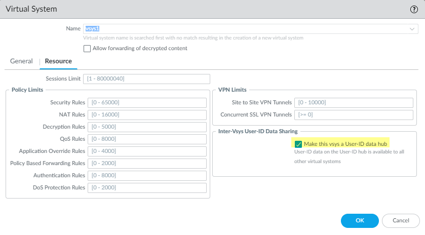
On the Resource tab, select Make
this vsys a User-ID data hub.
Click Yes to confirm, then
click OK.
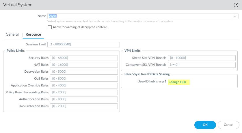
If you want to change the User-ID hub to a different virtual
system or disable it, select the virtual system currently configured
as a User-ID hub, then select ResourceChange Hub.
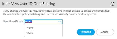
Select
the New User-ID hub from the list, or select none to
disable the User-ID hub and stop sharing mappings across virtual
systems.
Click Proceed to
confirm and commit your changes.
Commit the configuration.
Click Commit. The virtual system
is now an object accessible from the Objects tab.
Create at least one virtual router for the virtual system
in order to make the virtual system capable of networking functions,
such as static and dynamic routing.
Alternatively, your virtual system might use a VLAN or
a virtual wire, depending on your deployment.
Select NetworkVirtual Routers and Add a
virtual router by Name.
For Interfaces, click Add and
select the interfaces that belong to the virtual router.
Click OK.
Configure a security zone for each interface in the virtual
system.