Prisma SD-WAN
Configure a Sub-Interface
Table of Contents
Expand All
|
Collapse All
Prisma SD-WAN Docs
-
-
-
- CloudBlade Integrations
- CloudBlades Integration with Prisma Access
-
-
-
-
- 5.6
- 6.1
- 6.2
- 6.3
- 6.4
- 6.5
- New Features Guide
- On-Premises Controller
- Prisma SD-WAN CloudBlades
- Prisma Access CloudBlade Cloud Managed
- Prisma Access CloudBlade Panorama Managed
Configure a Sub-Interface
Let us learn to configure a sub-interface.
| Where Can I Use This? | What Do I Need? |
|---|---|
|
|
You can create sub-interfaces on physical
or virtual interfaces and use bypass pairs for Local Area Networks (LANs)
and private and public Wide Area Networks (WANs). A sub-interface
is created by dividing one physical interface into multiple virtual
interfaces.
The parent interface can be an Ethernet port,
a virtual port, or a bypass pair that does not contain any configuration.
You cannot configure a sub-interface on the controller port or any
interfaces or bypass pairs already configured with loopback as a
member with PPPoE or standard VPNs.
- If the sub-interface is on a bypass pair and the sub-interface is used for internet or private WAN, then the sub-interface is created on the bypass pair's WAN port.
- If the sub-interface is on a bypass pair and the sub-interface is used for LAN, then the sub-interface is created on the LAN port of the bypass pair.
Multiple sub-interfaces may be configured
on a physical or virtual interface or bypass pairs. If multiple
interfaces are configured, a VLAN ID is required to create and uniquely
identify each sub-interface.
Pre-5.1.x device releases,
LAN sub-interfaces may only be used for the following branch services. Release
5.1.1 and later device releases enable LAN sub-interfaces to
forward user and application traffic in addition to the following
branch services.
- DHCP Server
- DHCP Relay
- DHCP Relay source interface
- SNMP Agent
- SNMP Trap source interface
- Ping to and from the interface IP
- Secure Socket Shell (SSH) access to the ION device CLI commands
You
cannot configure a Virtual Interface (VI) on a sub-interface. DHCP
Relay and DHCP server cannot be configured on the same sub-interface.
DHCP Relay when configured on a sub-interface:
- Can listen to broadcast and unicast DHCP requests.
- Can use the sub-interface as the source interface to reach DHCP servers.
When SNMP is configured on a sub-interface:
- An SNMP Agent can listen to unicast requests.
- An SNMP Trap can use the sub-interface as the source interface to reach SNMP servers.
When Virtual Routing and Forwarding tables (VRF) is configured
on a sub-interface:
- Select LAN type interface for branch sites.
- Select Peer with the Network for data center sites.
- Select WorkflowsDevicesClaimed Devices, select the device you want to configure.Select the Interfaces tab.Select a port.For Admin Up, select Yes.(Optional) Enter a Description.Leave Use This Port To and IPv4 Configuration blank.For VRF, select Global or any other custom VRF listed. VRF Global is enabled only when the associated device supports VRF.Currently, VRF supports LAN. Configure the sub-interface individually, as the sub-interface configurations don’t inherit from the parent interface.Save Port.Click the Sub-Interfaces tab.Select + Add Sub-Interface to create a new sub-interface.For Admin Up, select Yes.(Optional) Enter a Description.From Use This Sub-Interface To drop-down, select the option applicable to the interface you are configuring; Connect to Internet, or Peer with a Network.For Circuit Label, select circuits and click Done.Enter a VLAN ID.The VLAN ID can be updated or changed.Mark the Native VLAN box if the identified sub-interface is used for native VLAN.Only one sub-interface of a parent interface can be configured for native VLAN. By default, the native VLAN box is unchecked.DNS Servers need to be entered for Internet and Private WAN but not for LAN.(Optional) If DHCP Relay functions are required, choose DHCP for the Configuration field. Change Add DHCP Relay from No to Yes.Select Create Sub-Interface.
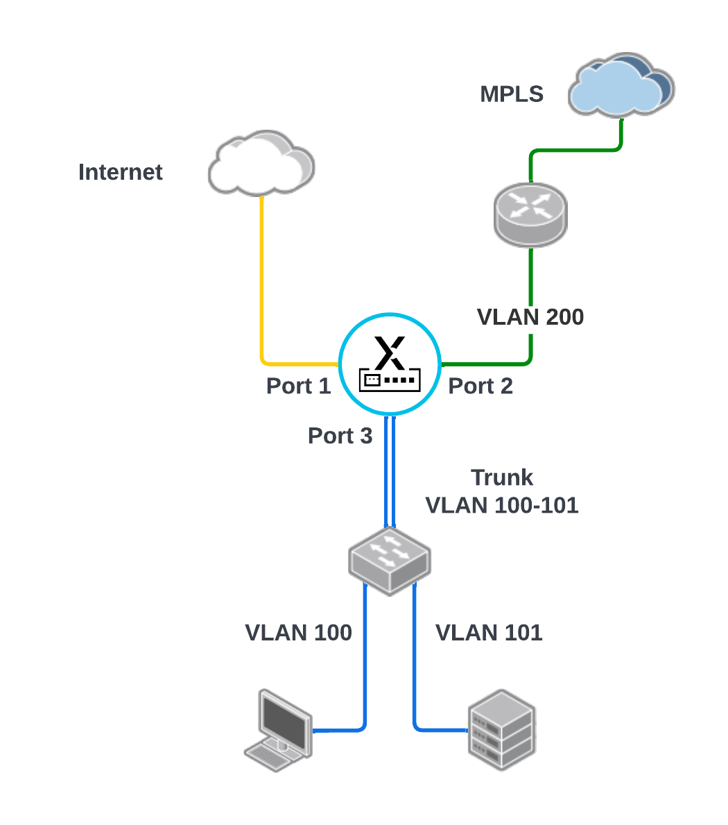
![]() The following use case shows a topology in which a sub-interface is used for the MPLS connection to the provider router on the WAN side. On the LAN side, there is a trunk interface with 2 VLANs (user and server) connected to a LAN switch.
The following use case shows a topology in which a sub-interface is used for the MPLS connection to the provider router on the WAN side. On the LAN side, there is a trunk interface with 2 VLANs (user and server) connected to a LAN switch.![]() The interface configuration summary for the above topology is as follows:
The interface configuration summary for the above topology is as follows:![]() Detailed configuration for LAN sub-interface 3.100
Detailed configuration for LAN sub-interface 3.100![]() Detailed configuration for LAN sub-interface 3.101
Detailed configuration for LAN sub-interface 3.101![]() Detailed configuration for WAN sub-interface 2.200
Detailed configuration for WAN sub-interface 2.200![]()


