Take a Custom Packet Capture
Table of Contents
Expand All
|
Collapse All
Next-Generation Firewall Docs
-
PAN-OS 10.0 (EoL)
- PAN-OS 11.1 & Later
- PAN-OS 11.0 (EoL)
- PAN-OS 10.2
- PAN-OS 10.1
- PAN-OS 10.0 (EoL)
- PAN-OS 9.1 (EoL)
- Cloud Management of NGFWs
-
- Management Interfaces
-
- Launch the Web Interface
- Configure Banners, Message of the Day, and Logos
- Use the Administrator Login Activity Indicators to Detect Account Misuse
- Manage and Monitor Administrative Tasks
- Commit, Validate, and Preview Firewall Configuration Changes
- Export Configuration Table Data
- Use Global Find to Search the Firewall or Panorama Management Server
- Manage Locks for Restricting Configuration Changes
-
-
- Define Access to the Web Interface Tabs
- Provide Granular Access to the Monitor Tab
- Provide Granular Access to the Policy Tab
- Provide Granular Access to the Objects Tab
- Provide Granular Access to the Network Tab
- Provide Granular Access to the Device Tab
- Define User Privacy Settings in the Admin Role Profile
- Restrict Administrator Access to Commit and Validate Functions
- Provide Granular Access to Global Settings
- Provide Granular Access to the Panorama Tab
- Provide Granular Access to Operations Settings
- Panorama Web Interface Access Privileges
-
- Reset the Firewall to Factory Default Settings
-
- Plan Your Authentication Deployment
- Configure SAML Authentication
- Configure Kerberos Single Sign-On
- Configure Kerberos Server Authentication
- Configure TACACS+ Authentication
- Configure RADIUS Authentication
- Configure LDAP Authentication
- Configure Local Database Authentication
- Configure an Authentication Profile and Sequence
- Test Authentication Server Connectivity
- Troubleshoot Authentication Issues
-
- Keys and Certificates
- Default Trusted Certificate Authorities (CAs)
- Certificate Deployment
- Configure the Master Key
- Export a Certificate and Private Key
- Configure a Certificate Profile
- Configure an SSL/TLS Service Profile
- Configure an SSH Service Profile
- Replace the Certificate for Inbound Management Traffic
- Configure the Key Size for SSL Forward Proxy Server Certificates
-
- HA Overview
-
- Prerequisites for Active/Active HA
- Configure Active/Active HA
-
- Use Case: Configure Active/Active HA with Route-Based Redundancy
- Use Case: Configure Active/Active HA with Floating IP Addresses
- Use Case: Configure Active/Active HA with ARP Load-Sharing
- Use Case: Configure Active/Active HA with Floating IP Address Bound to Active-Primary Firewall
- Use Case: Configure Active/Active HA with Source DIPP NAT Using Floating IP Addresses
- Use Case: Configure Separate Source NAT IP Address Pools for Active/Active HA Firewalls
- Use Case: Configure Active/Active HA for ARP Load-Sharing with Destination NAT
- Use Case: Configure Active/Active HA for ARP Load-Sharing with Destination NAT in Layer 3
- HA Clustering Overview
- HA Clustering Best Practices and Provisioning
- Configure HA Clustering
- Refresh HA1 SSH Keys and Configure Key Options
- HA Firewall States
-
- Use the Dashboard
- Monitor Applications and Threats
- Monitor Block List
-
- Report Types
- View Reports
- Configure the Expiration Period and Run Time for Reports
- Disable Predefined Reports
- Custom Reports
- Generate Custom Reports
- Generate the SaaS Application Usage Report
- Manage PDF Summary Reports
- Generate User/Group Activity Reports
- Manage Report Groups
- Schedule Reports for Email Delivery
- Manage Report Storage Capacity
- View Policy Rule Usage
- Use External Services for Monitoring
- Configure Log Forwarding
- Configure Email Alerts
-
- Configure Syslog Monitoring
-
- Traffic Log Fields
- Threat Log Fields
- URL Filtering Log Fields
- Data Filtering Log Fields
- HIP Match Log Fields
- GlobalProtect Log Fields
- IP-Tag Log Fields
- User-ID Log Fields
- Decryption Log Fields
- Tunnel Inspection Log Fields
- SCTP Log Fields
- Authentication Log Fields
- Config Log Fields
- System Log Fields
- Correlated Events Log Fields
- GTP Log Fields
- Syslog Severity
- Custom Log/Event Format
- Escape Sequences
- Forward Logs to an HTTP/S Destination
- Firewall Interface Identifiers in SNMP Managers and NetFlow Collectors
- Monitor Transceivers
-
- User-ID Overview
- Enable User-ID
- Map Users to Groups
- Enable User- and Group-Based Policy
- Enable Policy for Users with Multiple Accounts
- Verify the User-ID Configuration
-
- App-ID Overview
- App-ID and HTTP/2 Inspection
- Manage Custom or Unknown Applications
- Safely Enable Applications on Default Ports
- Applications with Implicit Support
- Application Level Gateways
- Disable the SIP Application-level Gateway (ALG)
- Maintain Custom Timeouts for Data Center Applications
-
- Best Practices for Securing Your Network from Layer 4 and Layer 7 Evasions
- Set Up Antivirus, Anti-Spyware, and Vulnerability Protection
- Set Up File Blocking
- Prevent Brute Force Attacks
- Customize the Action and Trigger Conditions for a Brute Force Signature
- Enable Evasion Signatures
- Monitor Blocked IP Addresses
- Threat Signature Categories
- Create Threat Exceptions
- Custom Signatures
- Share Threat Intelligence with Palo Alto Networks
- Threat Prevention Resources
-
- Decryption Overview
-
- Keys and Certificates for Decryption Policies
- SSL Forward Proxy
- SSL Forward Proxy Decryption Profile
- SSL Inbound Inspection
- SSL Inbound Inspection Decryption Profile
- SSL Protocol Settings Decryption Profile
- SSH Proxy
- SSH Proxy Decryption Profile
- Profile for No Decryption
- SSL Decryption for Elliptical Curve Cryptography (ECC) Certificates
- Perfect Forward Secrecy (PFS) Support for SSL Decryption
- SSL Decryption and Subject Alternative Names (SANs)
- TLSv1.3 Decryption
- High Availability Support for Decrypted Sessions
- Decryption Mirroring
- Configure SSL Forward Proxy
- Configure SSL Inbound Inspection
- Configure SSH Proxy
- Configure Server Certificate Verification for Undecrypted Traffic
- Enable Users to Opt Out of SSL Decryption
- Temporarily Disable SSL Decryption
- Configure Decryption Port Mirroring
- Verify Decryption
-
- How Decryption Broker Works
- Layer 3 Security Chain Guidelines
- Configure Decryption Broker with One or More Layer 3 Security Chain
- Transparent Bridge Security Chain Guidelines
- Configure Decryption Broker with a Single Transparent Bridge Security Chain
- Configure Decryption Broker with Multiple Transparent Bridge Security Chains
- Activate Free Licenses for Decryption Features
-
- About Palo Alto Networks URL Filtering Solution
- How Advanced URL Filtering Works
- URL Filtering Inline ML
- URL Filtering Use Cases
- Plan Your URL Filtering Deployment
- URL Filtering Best Practices
- Activate The Advanced URL Filtering Subscription
- Test URL Filtering Configuration
- Configure URL Filtering
- Configure URL Filtering Inline ML
- Log Only the Page a User Visits
- Create a Custom URL Category
- URL Category Exceptions
- Use an External Dynamic List in a URL Filtering Profile
- Allow Password Access to Certain Sites
- URL Filtering Response Pages
- Customize the URL Filtering Response Pages
- HTTP Header Logging
- Request to Change the Category for a URL
-
-
- Tap Interfaces
-
- Layer 2 and Layer 3 Packets over a Virtual Wire
- Port Speeds of Virtual Wire Interfaces
- LLDP over a Virtual Wire
- Aggregated Interfaces for a Virtual Wire
- Virtual Wire Support of High Availability
- Zone Protection for a Virtual Wire Interface
- VLAN-Tagged Traffic
- Virtual Wire Subinterfaces
- Configure Virtual Wires
- Configure an Aggregate Interface Group
- Configure Bonjour Reflector for Network Segmentation
- Use Interface Management Profiles to Restrict Access
- Virtual Routers
- Service Routes
- RIP
- Route Redistribution
-
- DNS Overview
- DNS Proxy Object
- DNS Server Profile
- Multi-Tenant DNS Deployments
- Configure a DNS Proxy Object
- Configure a DNS Server Profile
- Use Case 1: Firewall Requires DNS Resolution
- Use Case 2: ISP Tenant Uses DNS Proxy to Handle DNS Resolution for Security Policies, Reporting, and Services within its Virtual System
- Use Case 3: Firewall Acts as DNS Proxy Between Client and Server
- DNS Proxy Rule and FQDN Matching
- Dynamic DNS Overview
- Configure Dynamic DNS for Firewall Interfaces
-
- NAT Rule Capacities
- Dynamic IP and Port NAT Oversubscription
- Dataplane NAT Memory Statistics
-
- Translate Internal Client IP Addresses to Your Public IP Address (Source DIPP NAT)
- Enable Clients on the Internal Network to Access your Public Servers (Destination U-Turn NAT)
- Enable Bi-Directional Address Translation for Your Public-Facing Servers (Static Source NAT)
- Configure Destination NAT with DNS Rewrite
- Configure Destination NAT Using Dynamic IP Addresses
- Modify the Oversubscription Rate for DIPP NAT
- Reserve Dynamic IP NAT Addresses
- Disable NAT for a Specific Host or Interface
-
-
- Policy Types
- Policy Objects
- Track Rules Within a Rulebase
- Enforce Policy Rule Description, Tag, and Audit Comment
- Move or Clone a Policy Rule or Object to a Different Virtual System
-
- External Dynamic List
- Built-in External Dynamic Lists
- Configure the Firewall to Access an External Dynamic List
- Retrieve an External Dynamic List from the Web Server
- View External Dynamic List Entries
- Exclude Entries from an External Dynamic List
- Enforce Policy on an External Dynamic List
- Find External Dynamic Lists That Failed Authentication
- Disable Authentication for an External Dynamic List
- Register IP Addresses and Tags Dynamically
- Use Dynamic User Groups in Policy
- Use Auto-Tagging to Automate Security Actions
- CLI Commands for Dynamic IP Addresses and Tags
- Test Policy Rules
-
- Network Segmentation Using Zones
- How Do Zones Protect the Network?
-
PAN-OS 11.1 & Later
- PAN-OS 11.1 & Later
- PAN-OS 11.0 (EoL)
- PAN-OS 10.2
- PAN-OS 10.1
-
- Tap Interfaces
-
- Layer 2 and Layer 3 Packets over a Virtual Wire
- Port Speeds of Virtual Wire Interfaces
- LLDP over a Virtual Wire
- Aggregated Interfaces for a Virtual Wire
- Virtual Wire Support of High Availability
- Zone Protection for a Virtual Wire Interface
- VLAN-Tagged Traffic
- Virtual Wire Subinterfaces
- Configure Virtual Wires
- Configure a PPPoE Client on a Subinterface
- Configure an IPv6 PPPoE Client
- Configure an Aggregate Interface Group
- Configure Bonjour Reflector for Network Segmentation
- Use Interface Management Profiles to Restrict Access
-
- DHCP Overview
- Firewall as a DHCP Server and Client
- Firewall as a DHCPv6 Client
- DHCP Messages
- Dynamic IPv6 Addressing on the Management Interface
- Configure an Interface as a DHCP Server
- Configure an Interface as a DHCPv4 Client
- Configure an Interface as a DHCPv6 Client with Prefix Delegation
- Configure the Management Interface as a DHCP Client
- Configure the Management Interface for Dynamic IPv6 Address Assignment
- Configure an Interface as a DHCP Relay Agent
-
- DNS Overview
- DNS Proxy Object
- DNS Server Profile
- Multi-Tenant DNS Deployments
- Configure a DNS Proxy Object
- Configure a DNS Server Profile
- Use Case 1: Firewall Requires DNS Resolution
- Use Case 2: ISP Tenant Uses DNS Proxy to Handle DNS Resolution for Security Policies, Reporting, and Services within its Virtual System
- Use Case 3: Firewall Acts as DNS Proxy Between Client and Server
- DNS Proxy Rule and FQDN Matching
-
- NAT Rule Capacities
- Dynamic IP and Port NAT Oversubscription
- Dataplane NAT Memory Statistics
-
- Translate Internal Client IP Addresses to Your Public IP Address (Source DIPP NAT)
- Create a Source NAT Rule with Persistent DIPP
- PAN-OS
- Strata Cloud Manager
- Enable Clients on the Internal Network to Access your Public Servers (Destination U-Turn NAT)
- Enable Bi-Directional Address Translation for Your Public-Facing Servers (Static Source NAT)
- Configure Destination NAT with DNS Rewrite
- Configure Destination NAT Using Dynamic IP Addresses
- Modify the Oversubscription Rate for DIPP NAT
- Reserve Dynamic IP NAT Addresses
- Disable NAT for a Specific Host or Interface
-
- Network Packet Broker Overview
- How Network Packet Broker Works
- Prepare to Deploy Network Packet Broker
- Configure Transparent Bridge Security Chains
- Configure Routed Layer 3 Security Chains
- Network Packet Broker HA Support
- User Interface Changes for Network Packet Broker
- Limitations of Network Packet Broker
- Troubleshoot Network Packet Broker
-
- Enable Advanced Routing
- Logical Router Overview
- Configure a Logical Router
- Create a Static Route
- Configure BGP on an Advanced Routing Engine
- Create BGP Routing Profiles
- Create Filters for the Advanced Routing Engine
- Configure OSPFv2 on an Advanced Routing Engine
- Create OSPF Routing Profiles
- Configure OSPFv3 on an Advanced Routing Engine
- Create OSPFv3 Routing Profiles
- Configure RIPv2 on an Advanced Routing Engine
- Create RIPv2 Routing Profiles
- Create BFD Profiles
- Configure IPv4 Multicast
- Configure MSDP
- Create Multicast Routing Profiles
- Create an IPv4 MRoute
-
-
PAN-OS 11.2
- PAN-OS 11.2
- PAN-OS 11.1
- PAN-OS 11.0 (EoL)
- PAN-OS 10.2
- PAN-OS 10.1
- PAN-OS 10.0 (EoL)
- PAN-OS 9.1 (EoL)
- PAN-OS 9.0 (EoL)
- PAN-OS 8.1 (EoL)
- Cloud Management and AIOps for NGFW
End-of-Life (EoL)
Take a Custom Packet Capture
Custom packet captures allow you to define
the traffic that the firewall will capture. To ensure that you capture
all traffic, you may need to Disable Hardware Offload.
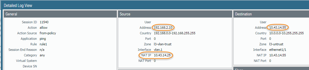
- Before you start a packet capture, identify the
attributes of the traffic that you want to capture.For example, to determine the source IP address, source NAT IP address, and the destination IP address for traffic between two systems, perform a ping from the source system to the to the destination system. After the ping is complete, go to MonitorTraffic and locate the traffic log for the two systems. Click the Detailed Log View icon located in the first column of the log and note the source address, source NAT IP, and the destination address.
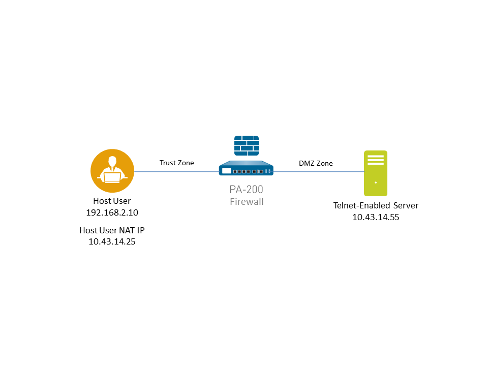
The following example shows how to use a packet capture to troubleshoot a Telnet connectivity issue from a user in the Trust zone to a server in the DMZ zone.
- Set packet capture filters, so the firewall only captures
traffic you are interested in.Using filters makes it easier for you to locate the information you need in the packet capture and will reduce the processing power required by the firewall to take the packet capture. To capture all traffic, do not define filters and leave the filter option off.For example, if you configured NAT on the firewall, you will need to apply two filters. The first one filters on the pre-NAT source IP address to the destination IP address and the second one filters traffic from the destination server to the source NAT IP address.
- Select MonitorPacket Capture.
- Click Clear All Settings at the bottom of the window to clear any existing capture settings.
- Click Manage Filters and click Add.
- Select Id 1 and in the Source field
enter the source IP address you are interested in and in the Destination field
enter a destination IP address.For example, enter the source IP address 192.168.2.10 and the destination IP address 10.43.14.55. To further filter the capture, set Non-IP to exclude non-IP traffic, such as broadcast traffic.
- Add the second filter and select Id 2.For example, in the Source field enter 10.43.14.55 and in the Destination field enter 10.43.14.25. In the Non-IP drop-down menu select exclude.
- Click OK.
- Set Filtering to On.
- Specify the traffic stage(s) that trigger the packet
capture and the filename(s) to use to store the captured content.
For a definition of each stage, click the Help icon
on the packet capture page.For example, to configure all packet capture stages and define a filename for each stage, perform the following procedure:
- Add a Stage to
the packet capture configuration and define a File name
for the resulting packet capture.For example, select receive as the Stage and set the File name to telnet-test-received.
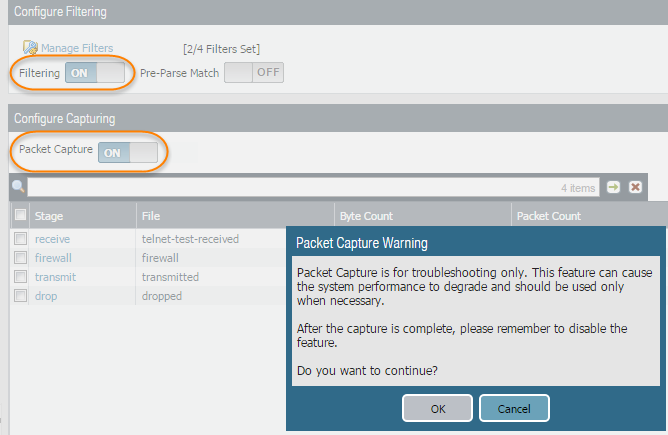
- Continue to Add each Stage you
want to capture (receive, firewall, transmit, and drop)
and set a unique File name for each stage.
- Add a Stage to
the packet capture configuration and define a File name
for the resulting packet capture.
- Set Packet Capture to ON.The firewall or appliance warns you that system performance can be degraded; acknowledge the warning by clicking OK. If you define filters, the packet capture should have little impact on performance, but you should always turn Off packet capture after the firewall captures the data that you want to analyze.
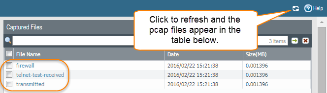
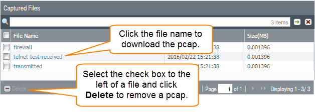
- Generate traffic that matches the filters that you defined.For this example, generate traffic from the source system to the Telnet-enabled server by running the following command from the source system (192.168.2.10):telnet 10.43.14.55
- Turn packet capture OFF and then
click the refresh icon to see the packet capture files.Notice that in this case, there were no dropped packets, so the firewall did not create a file for the drop stage.
- Download the packet captures by clicking the filename
in the File Name column.
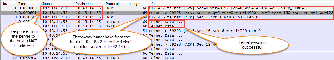
- View the packet capture files using a network packet
analyzer.In this example, the received.pcap packet capture shows a failed Telnet session from the source system at 192.168.2.10 to the Telnet-enabled server at 10.43.14.55. The source system sent the Telnet request to the server, but the server did not respond. In this example, the server may not have Telnet enabled, so check the server.
- Enable the Telnet service on the destination server (10.43.14.55) and turn on packet capture to take a new packet capture.
- Generate traffic that will trigger the packet capture.Run the Telnet session again from the source system to the Telnet-enabled servertelnet 10.43.14.55
- Download and open the received.pcap file and view it
using a network packet analyzer.The following packet capture now shows a successful Telnet session from the host user at 192.168.2.10 to the Telnet-enabled server at 10.43.14.55.You also see the NAT address 10.43.14.25. When the server responds, it does so to the NAT address. You can see the session is successful as indicated by the three-way handshake between the host and the server and then you see Telnet data.