Prisma Access
Integrate Prisma Access with Cisco Catalyst SD-WAN (Manual Integration) (Panorama)
Table of Contents
Expand All
|
Collapse All
Prisma Access Docs
-
- 6.1 Preferred and Innovation
- 6.0 Preferred and Innovation
- 5.2 Preferred and Innovation
- 5.1 Preferred and Innovation
- 5.0 Preferred and Innovation
- 4.2 Preferred
- 4.1 Preferred
- 4.0 Preferred
- 3.2 Preferred and Innovation
- 3.1 Preferred and Innovation
- 3.0 Preferred and Innovation
- 2.2 Preferred
-
-
- 4.0 & Later
- Prisma Access China
-
-
Integrate Prisma Access with Cisco Catalyst SD-WAN (Manual Integration) (Panorama)
You can configure the IPSec tunnel in Prisma Access before you perform the IPSec
tunnel configuration in Cisco Catalyst.
Before you start, get the IP address of the Cisco Catalyst SD-WAN device that you
will be using as the other side of the remote network connection; you enter this
information in your IKE Gateway profile.
- In Panorama, add an IPSec crypto profile, IKE crypto profile, IKE gateway, and IPSec tunnel in the Remote_Network_Template template.
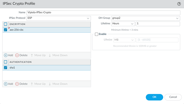
- Select NetworkNetwork ProfilesIPSec Crypto and Add an IPSec Crypto Profile, specifying supported Encryption and Authentication settings; then click OK.Be sure that you have selected the Remote_Network_Template in the Templates drop-down at the top of the page.
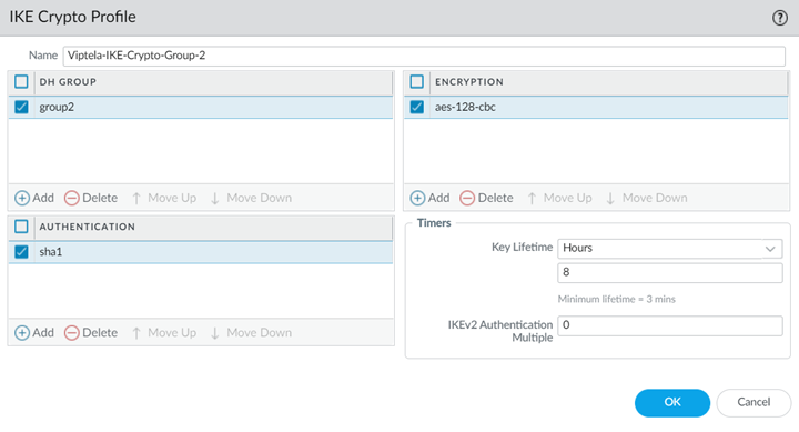
![]() Select Network ProfilesIKE Crypto and Add an IKE Crypto Profile specifying supported DH Group, Encryption, and Authentication settings; then click OK.
Select Network ProfilesIKE Crypto and Add an IKE Crypto Profile specifying supported DH Group, Encryption, and Authentication settings; then click OK.![]() Select Network ProfilesIKE Gateways and Add an IKE Gateway.
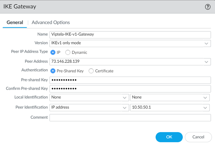
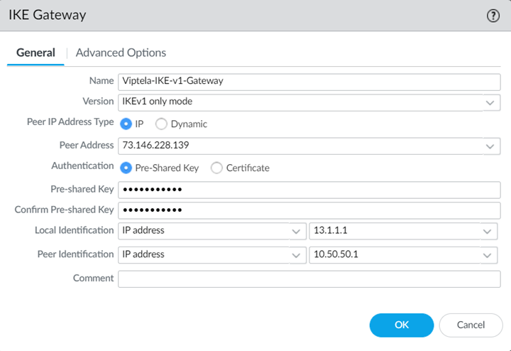
Select Network ProfilesIKE Gateways and Add an IKE Gateway.- Specify the following values in the General tab:
- Select a Peer IP Address Type of IP and enter the IP address of the Cisco Catalyst SD-WAN device that you will be using as the other side of the remote network connection as the Peer Address.
- If using a pre-shared key for the IPSec tunnel, specify a Pre-shared Key.
- Leave Local Identification blank, because you do not know what this address is at the time of configuration; you add this later at the end of the procedure in Step 5.
- Specify a Peer Identification of either IP Address or User FQDN.Be sure that you match the settings you specify here when you configure the device used to terminate the other side of the Cisco Catalyst IPSec tunnel.
![]()
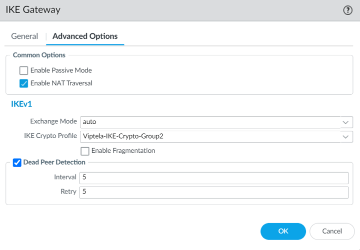
- Select the following values in the Advanced Options tab:
- Select Enable NAT Traversal.NAT traversal is required because the Cisco Catalyst SD-WAN uses the IP address from the LAN side of the SD-WAN device as the source interface. As a result, all traffic undergoes NAT translation on the interface used for the remote network connection (that is, the WAN side of the Cisco Catalyst SD-WAN).With the NAT Traversal option enabled, Prisma Access performs UDP encapsulation on IKE and UDP protocols, enabling them to pass through intermediate NAT devices.
- Select the IKE Crypto Profile you created in Step 1.b.
![]()
- Click OK when complete.
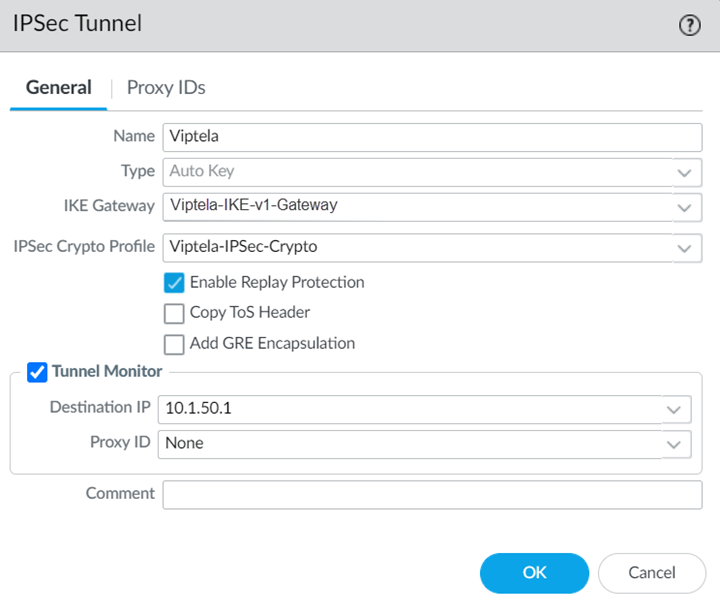
Select IPSec Tunnels and Add an IPSec Tunnel, specifying the IKE Gateway and IPSec Crypto Profile you just created.![]() (Optional) Select Tunnel Monitor and specify a Destination IP address that can monitor reachability of the IPSec tunnel between Prisma Access and the Cisco Catalyst SD-WAN.Make a note of this address; you match this address with the loopback100 interface you assign to the Cisco Catalyst SD-WAN when you configure the remote network connection in Cisco Catalyst.Make a note of all IKE and IPSec settings you used in the tunnel configuration.Onboard your remote network connection and enter the following values:
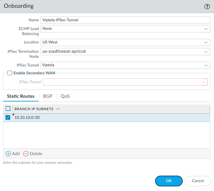
(Optional) Select Tunnel Monitor and specify a Destination IP address that can monitor reachability of the IPSec tunnel between Prisma Access and the Cisco Catalyst SD-WAN.Make a note of this address; you match this address with the loopback100 interface you assign to the Cisco Catalyst SD-WAN when you configure the remote network connection in Cisco Catalyst.Make a note of all IKE and IPSec settings you used in the tunnel configuration.Onboard your remote network connection and enter the following values:- Specify a Name, Bandwidth, and Region.
- Select the IPSec Tunnel profile you created in Step 1.d.
- Specify a Branch IP Subnet that is significant to Cisco Catalyst.A /30 subnet is sufficient for a Cisco Catalyst-Prisma Access SD-WAN integration, because you need only two IP addresses for this configuration:
- 10.10.10.1, which you specified as the IP address for the ge0/4 interface.
- 10.10.10.2, for which you specify a default route when you configure the remote network connection in Cisco Catalyst.
![]() Commit the configuration changes to Panorama and push the configuration out to Prisma Access for remote networks.
Commit the configuration changes to Panorama and push the configuration out to Prisma Access for remote networks.- Click CommitCommit to Panorama.Click CommitCommit and Push. Click Edit SelectionsPrisma Access, and select both Prisma Access for remote networks and Prisma Access for service setup to push the configuration out to the service.
![]() Click OK and Push.Complete configuration of the IKE Gateway.
Click OK and Push.Complete configuration of the IKE Gateway.- Select PanoramaCloud ServicesStatusNetwork Details, click the Remote Networks tab, and make a note of the Service IP Address.Select Network ProfilesIKE Gateways and select the IKE Gateway you specified in Step 1.c.Change Local Identification to IP address and add the Service IP Address you just retrieved (13.1.1.1 in this example).
![]() Be sure to make a note of the Service IP Address; you must configure this as the peer IP address to set up the IPSec tunnel between the Cisco Catalyst SD-WAN device and Prisma Access.
Be sure to make a note of the Service IP Address; you must configure this as the peer IP address to set up the IPSec tunnel between the Cisco Catalyst SD-WAN device and Prisma Access.Create a Remote Network Connection in Cisco Catalyst
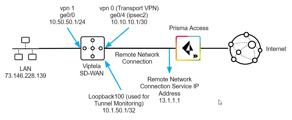
Use the following steps to configure the IPSec tunnel in Cisco Catalyst. The examples in this section use command-line interface (CLI) commands.This configuration completes the remote network connection between Prisma Access and the Cisco Catalyst SD-WAN. The following figure shows what you define in the Cisco Catalyst side:- On the LAN side of the Cisco Catalyst SD-WAN device, create a ge0/0 interface with an IP address of 10.50.50.1. This matches the IP address you specified when you configured the IKE Gateway in Prisma Access.The Cisco Catalyst SD-WAN performs NAT on the source IP address for the LAN (73.146.228.139).
- On the remote network tunnel (WAN) side, create an interface named ipsec2 with a type, slot, and port of ge0/4 whose IP address is 10.10.10.1/30.This address must be within the subnet range you specified for the Branch IP Subnet when you onboarded your remote network in Prisma Access. In this example, the administrator specified a Branch IP Subnet of 10.10.10.0/30 in Prisma Access, and you use the other available IP address (10.10.10.1/30) on the Cisco Catalyst side of the remote network connection.
- Specify a tunnel-destination IP address that matches the Prisma Access Service IP Address. This example uses 13.1.1.1.
- Specify a loopback IP address that Prisma Access can use for tunnel monitoring.In this example, the administrator configured a loopback100 interface with an IP address of 10.1.50.1/32. This value matches the Tunnel Monitor Destination IP address you specified in the IPSec Tunnel configuration that you configured in Prisma Access.
![]()
- Open a CLI session with the Cisco Catalyst SD-WAN device and enter the following commands to define the control plane for the Cisco Catalyst Overlay Management Protocol (OMP).The following commands enable a graceful restart for the OMP and advertise static and connected routes.
omp
 no shutdown
 graceful-restart
 advertise connected
 advertise static
Define the security types for the IPSec tunnel.The following commands enable the AH-SHA1 HMAC and ESP HMAC-SHA1 authentication types.security ipsec authentication-type sha1-hmac ah-sha1-hmac
Configure VPNs to segment the Cisco Catalyst overlay network.The following commands create a VPN VPN 0 named Transport VPN and associates the ge0/4 interface with this VPN. You use this interface and VPN for the Cisco Catalyst SD-WAN side of the remote network tunnel (IPSec tunnel) between Cisco Catalyst and Prisma Access.vpn 0 name "Transport VPN" interface ge0/4 ip dhcp-client tunnel-interface encapsulation ipsec color biz-internet allow-service all no allow-service bgp allow-service dhcp allow-service dns allow-service icmp no allow-service sshd no allow-service netconf no allow-service ntp no allow-service ospf no allow-service stun
Enter the no shutdown command to enable the ge0/4 interface.Create another VPN named VPN 1, associate the ge0/0 interface with this VPN, then define parameters for it.The following example defines the parameters to allow the Cisco Catalyst SD-WAN to route traffic from the LAN to its ge0/0 interface.vpn 1 interface ge0/0 ip address 10.50.50.1/24 no shutdown dhcp-server address-pool 10.50.50.0/24 exclude 10.50.50.1 offer-time 600 lease-time 86400 admin-state up options default-gateway 10.50.50.1 dns-servers 8.8.8.8 8.8.4.4Create an interface named ipsec2 and apply it to the ge0/4 interface. These commands define the parameters for the remote network tunnel between the Cisco Catalyst SD-WAN and Prisma Access.Enter the following values:- Enter an ip address to allow the Cisco Catalyst SD-WAN to route traffic to Prisma Access.This address must be within the subnet range you specified for the Branch Subnet when you onboarded your remote network in Prisma Access. A /30 address is sufficient to allow routing to Prisma Access.
- Specify the same tunnel-source-interface that you used for VPN 0 (ge0/4 in this example).
- Specify a tunnel-destination using the Service IP Address from Prisma Access. This example uses 13.1.1.1 as the Service IP Address.
- Make sure that the ike and ipsec parameters that you specify match the parameters you specified in Prisma Access.
- Enter a pre-shared-secret that matches the Pre-shared key (PSK) that you entered in Prisma Access. This example uses a PSK of secretkey.
 interface ipsec2
  ip address 10.10.10.1/30
  tunnel-source-interface ge0/4
  tunnel-destination      13.1.1.1
  ike
   version      1
   mode         main
   rekey        14400
   cipher-suite aes128-cbc-sha1
   group        2
   authentication-type
    pre-shared-key
     pre-shared-secret secretkey
    !
   !
  !
  ipsec
   rekey         3600
   replay-window 512
   cipher-suite  aes256-cbc-sha1
Enter the no shutdown command on the ipsec2 interface to enable it.Create a loopback interface to be used for tunnel monitoring.interface loopback100 ip address 10.1.50.1/32 no shutdown
Create a default route for the network.This route uses the second IP address (10.10.10.2 in this example) of the /30 subnet you used when you onboarded your remote network in Prisma Access. The Cisco Catalyst side of the network can route to this IP address and uses it as a next hop for routing.ip route 0.0.0.0/0 10.10.10.2
Enter a VPN and give it a name.vpn 512 name "Transport VPN"
Apply policies for the network.policy app-visibility flow-visibility
Troubleshoot the Cisco Catalyst Remote Network
To troubleshoot problems related to SD-WAN tunnels in Cisco Catalyst, refer to the Cisco Catalyst documentation for configuring IPSec tunnels at the following URL: https://www.cisco.com/c/en/us/support/routers/sd-wan/tsd-products-support-series-home.html.To troubleshoot issues in Prisma Access, we provide logs that provide you with the status of remote tunnels and the status of each tunnel. To view these logs in Panorama, select MonitorLogsSystem.To debug tunnel issues, you can filter for tunnel-specific logs by using the object identifier corresponding to that tunnel. The following figures show errors related to tunnel misconfiguration and negotiation issues.![]()
![]()
![]()
![]()
![]()
![]()

