Prisma SD-WAN
Configure Branch HA with Gen-2 Embedded Switch Platforms (1200-S or 3200-L2)
Table of Contents
Configure Branch HA with Gen-2 Embedded Switch Platforms (1200-S or 3200-L2)
Learn how to configure branch HA with Gen-2 embedded switch platforms in Prisma SD-WAN.
| Where Can I Use This? | What Do I Need? |
|---|---|
|
|
The example showcases two ION 1200-S or ION 3200 (in L2 mode) devices,
representing the next generation of software-defined enterprise technology. These
devices feature switch ports, cellular 5G/LTE technologies (ION 1200-S), and 802.1x
authentication capabilities.

The topology has the following features:
- The active device has one Internet connection.
- The backup device has one MPLS/Private connection.
- The ION devices operate in an active/backup configuration, and through fail-to-wire functionality, the active ION constantly maintains complete control and utilizes the full capacity of all the WAN circuits.
- The devices establish a connection through a trunk, facilitating both data connectivity and enabling High Availability (HA) via device heartbeat monitoring. This connection can be established either with a south-bound switch or directly between the devices, eliminating the necessity for additional LAN switch hardware at the site.If the devices are directly connected and they lose connectivity with each other, both will transition to an Active/Active state, continuing to serve outbound connections. However, inbound connections will remain inactive until High Availability (HA) is re-established.Directly establishing the High Availability (HA) connection between devices is recommended only in cases where there are no southbound switches present at the branch.
- The LAN addressing is identical on both devices, permitting only the active device to use Address Resolution Protocol (ARP) and communicate with hosts and network devices in the LAN.
- The High Availability (HA) addressing is unique, enabling the backup device to communicate with the controller through the active device for connectivity.
- Prisma SD-WAN facilitates the utilization of both the fabric overlay and the underlay (private MPLS). If you opt for the underlay, it's imperative to configure the necessary routing exchange between the ION device and the PE (peer edge) router.

- Create physical connections between the interfaces of the active and backup ION device.
- Connect Port 4 of ION 1 to Port 1 of ION 2. (Internet).Connect Port 4 of ION 2 to Port 1 of ION 1. (MPLS).This ensures that the Internet and MPLS circuits are available to both the ION devices.Configure bypass pairs for each ION device.
- Between Ports 3 and 4 of the active ION device. (Port 3—WAN (Internet), Port 4—LAN)
- Between Ports 3 and 4 of the standby ION device. (Port 3—WAN (MPLS), Port 4—LAN)
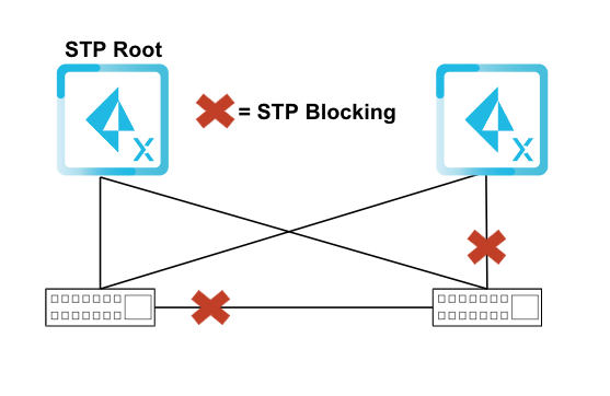
Prisma SD-WAN facilitates the utilization of both the fabric overlay and the underlay (private MPLS). If you opt for the underlay, it's imperative to configure the necessary routing exchange between the ION device and the PE router.Configure the High Availability (Used-for-HA) interface.In this example, we are configuring SVI 130 as the Used-for-HA interface for heartbeat exchange between the devices.The interface designated for handling High Availability (HA) will be responsible for establishing connections between the devices and the controller. Consequently, it is crucial that these interfaces possess external reachability (direct or via overlay) and are configured with DNS servers capable of resolving public addresses.Configure an SVI interface for LAN connectivity.In this example, we are configuring SVI 100 for LAN connectivity to enable data exchange.You can use a single interface to transit to a layer 3 switch below, or alternatively, you can create multiple LAN subinterfaces and ports to communicate directly with different host subnets.If using a transit LAN to a layer 3 switch, you must also set up routing accordingly.Configure a trunk port for the LAN and HA SVIs.In this instance, we are configuring a trunk port on port 5, where both the LAN (SVI 100) and HA SVI (SVI 130) are assigned. Both the Ports 5 on the ION devices will be directly connected to the LAN switch.The embedded Layer 2 switch on the ION 1200-S and 3200 operates via Multiple Spanning Tree Protocol (MSTP) when in layer 2 mode. When integrating these switches with neighboring LAN switches, it's crucial to note that the adjacent switches should not operate using Per VLAN Spanning-Tree (PVST). Instead, they should use MSTP (which is Rapid Spanning Tree Protocol (RSTP) backwards compatible).For redundancy purposes, trunk ports can be connected to redundant switches. With the implementation of MSTP, it ensures the creation of a loop-free topology, thus maintaining network stability.![]() Add the ION Devices to the HA Groups.Enable Interface tracking for the trunk switch ports to ensure correct fail-over behavior. Ensure that the tracking decrement value is the same as the existing device HA priority in order for the ION device to decrement to zero under this failure condition.
Add the ION Devices to the HA Groups.Enable Interface tracking for the trunk switch ports to ensure correct fail-over behavior. Ensure that the tracking decrement value is the same as the existing device HA priority in order for the ION device to decrement to zero under this failure condition.