Prisma Access
Create a High-Bandwidth Network for a Remote Site
Table of Contents
Create a High-Bandwidth Network for a Remote Site
Create a high-bandwidth network for a remote site by
combining multiple Prisma Access remote network connections.
| Where Can I Use This? | What Do I Need? |
|---|---|
|
|
If you want to secure your branch office or site for
outbound internet access with a high-bandwidth connection to Prisma
Access, you can load balance traffic from your branch office or
site using multiple IPSec tunnels by completing the steps in this section.
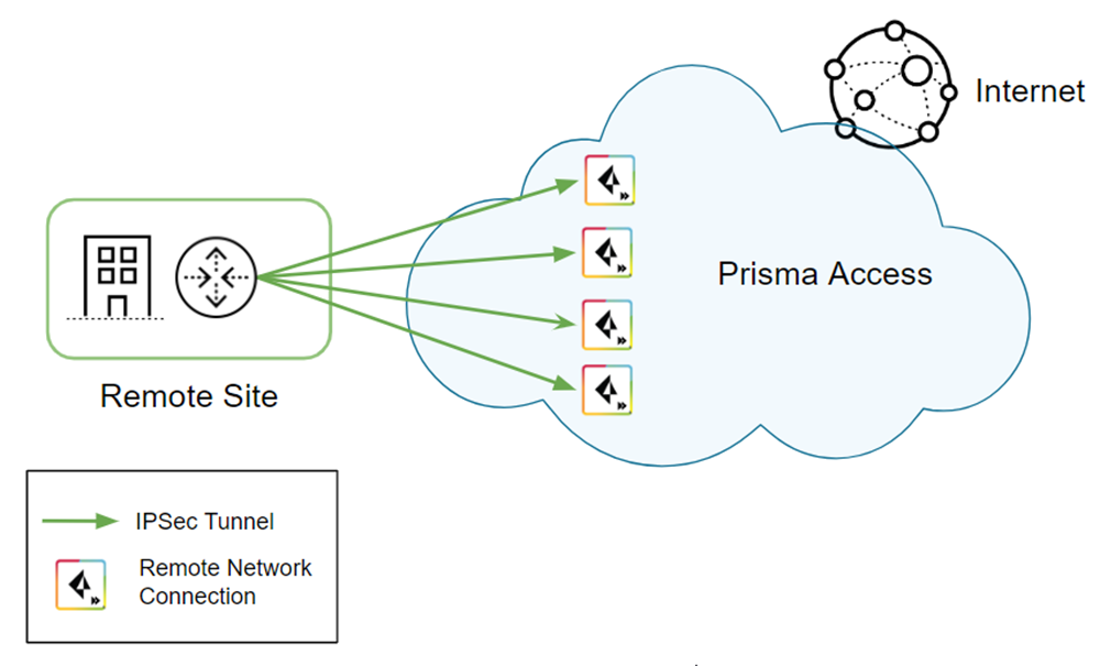
The
following diagram shows four remote network connections that use
the same remote site. Before onboarding, assign 4 Gbps (4000 Mbps)
to the compute location, which is South Korea in this example and
corresponds to the remote site. 4000 Mbps provides four IPSec termination
nodes and each IPSec termination node provides a maximum of 1000
Mbps of bandwidth. Assign each remote network connection its own
IPSec termination node during the onboarding process to utilize
the complete bandwidth.
This example shows four tunnels.
The maximum number of tunnels you can use for a high-bandwidth connection in
Prisma Access is based on the maximum number of IPSec tunnels your
customer premises equipment (CPE) support with the load balancing
protocol you use.
Consider
the following restrictions and recommendations before you deploy
this configuration:
- Use BGP routing for the IPSec tunnels; static routing is not supported.
- Use this configuration for outbound internet access only.
- Do not use tunnel monitoring on either Prisma Access or the CPE. Availability of the IPSec tunnel is determined by BGP peering between the CPE and Prisma Access’ remote network. If an IPSec tunnel goes down and BGP connection is interrupted, the routes learned over BGP on that tunnel are automatically removed from ECMP.
- Because you use BGP to determine when a tunnel goes down, consider the HoldTime value you have configured on your CPE. The hold timer determines the amount of time that the tunnel is down before removing the route. Prisma Access uses the default BGP HoldTime value of 90 seconds as defined by RFC 4271. If you configure a lower hold time for the BGP CPE in the remote network site, BGP uses the lower hold time value. Palo Alto Networks recommends a KeepAlive value of 10 seconds and a HoldTime value of 30 seconds for your CPE with this deployment.
To create a high-bandwidth remote network connection, complete the following
task.
- in Panorama, configure the Prisma Access remote network tunnels.
- (Optional) if you haven’t already, set up IKE gateways, IKE crypto and IPSec crypto profiles, and IPSec tunnels for the remote network connections you create.Make a note of the IKE and IPSec cryptographic profiles; you specify the same settings on the CPE you use to terminate the remote network connection in the remote network location.Determine the type of remote network deployment you have.Prisma Access deployments allocate bandwidth by allocating bandwidth per compute location or by allocating bandwidth by location.Onboard the remote network.
- To onboard the remote network that allocates bandwidth by compute location:
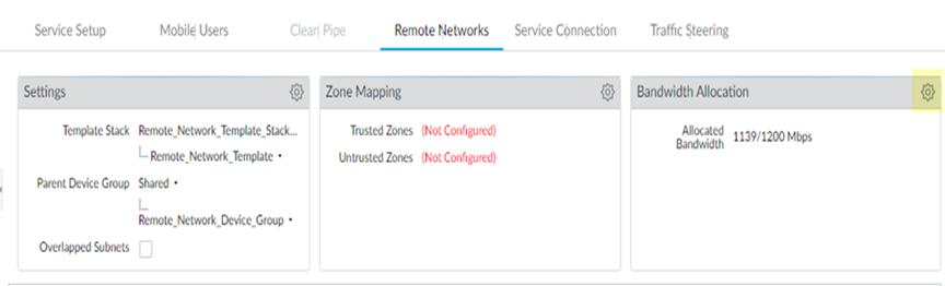
- Allocate bandwidth for the locations that you want to onboard by clicking the gear icon in the Bandwidth Allocation area.
![]()
- Enter the Bandwidth Allocation you want for each Compute Location that is associated with the Prisma Access Locations you want to onboard.
- Wait for the bandwidth to be reflected in the Allocated Total field at the top of the page; then, click OK.
- To onboard the remote network that allocates bandwidth by location, continue to the next step; you allocate bandwidth during remote network onboarding.
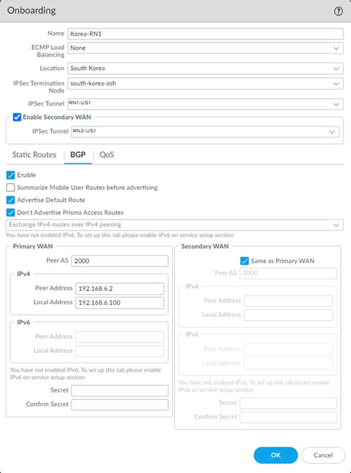
Select and create four remote networks connections, specifying the following settings:- Select the same Location for each connection.
- Select the IPSec Termination Node.Select a separate IPSec termination node for each remote network connection.If you have a deployment that allocates bandwidth by location, select a Bandwidth of 500 Mbps.The bandwidth you select cannot exceed the total amount of bandwidth you have licensed. Use this setting to define the amount of the total licensed bandwidth you want to allocate to this location.
- Enable BGP, Advertise Default Route, and Don’t Advertise Prisma Access Routes.
- Specify the same Peer AS for all remote network connections.This example shows a Peer AS of 2000; in this example, you select a Peer AS of 2000 for all four connections.
- (Optional) if you want to create a backup remote network, create one by selecting Enable Secondary WAN; then, select the IPSec Tunnel you created for the backup tunnel.
Configuring a Secondary WAN is not supported in the following deployments:- If your secondary WAN is set up in active-active mode with the Primary IPSec tunnel.
- If your customer premises equipment (CPE) is set up in an Equal Cost Multipath (ECMP) configuration with the Primary and Secondary IPSec tunnel.
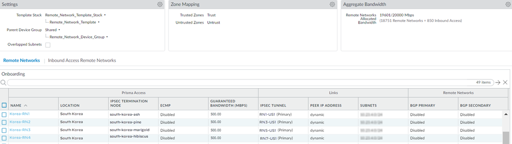
![]() When complete, you have four 1000 Mbps remote network connections for the same location.Since deployments that allocate bandwidth by location have a maximum bandwidth of 500 Mbps, this configuration would provide you with 500 Mbps for each location.If you configured backup tunnels, you also have four secondary tunnels to be used for failover purposes.
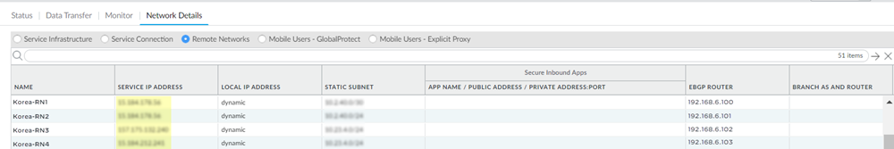
When complete, you have four 1000 Mbps remote network connections for the same location.Since deployments that allocate bandwidth by location have a maximum bandwidth of 500 Mbps, this configuration would provide you with 500 Mbps for each location.If you configured backup tunnels, you also have four secondary tunnels to be used for failover purposes.![]() Select and make a note of the Service Endpoint Address and EBGP Router addresses.You use the Service Endpoint Address as the peer FQDN or IP address when you configure the IPSec tunnel on the CPE in the remote network site, and you use these addresses and the EBGP Router addresses when you create static routes on the CPE.
Select and make a note of the Service Endpoint Address and EBGP Router addresses.You use the Service Endpoint Address as the peer FQDN or IP address when you configure the IPSec tunnel on the CPE in the remote network site, and you use these addresses and the EBGP Router addresses when you create static routes on the CPE.![]() On the CPE in the remote network site, configure the remote network tunnels.
On the CPE in the remote network site, configure the remote network tunnels.- The configuration in these steps use Palo Alto Networks next-generation firewalls; you can use any CPE device that supports IPSec tunnels and ECMP for this deployment.
- Bandwidth balancing depends on CPE hashing for ECMP. However, Prisma Access ensures symmetrical return of traffic.
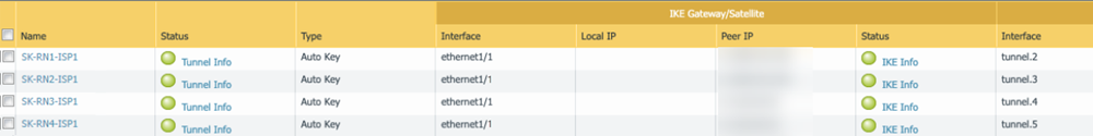
- Create four active tunnels from the active CPE to each of the four network connections. For the Peer IP address, enter the Service Endpoint Address of the remote network you received from Prisma Access in a previous step.
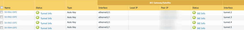
![]() (Optional) If you create backup tunnels, create them from the active CPE to each of the four network connections. For the Peer IP address, enter the Service Endpoint Address of the remote network you received from Prisma Access in a previous step.
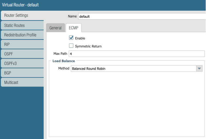
(Optional) If you create backup tunnels, create them from the active CPE to each of the four network connections. For the Peer IP address, enter the Service Endpoint Address of the remote network you received from Prisma Access in a previous step.![]() Configure ECMP on the CPE in the remote network site.
Configure ECMP on the CPE in the remote network site.- Select .Select the default virtual router, or Add a new virtual router.Select , then Enable ECMP with a Max Path of 4 and a load balance Method of Balanced Round Robin.
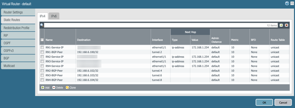
![]() On the CPE in the remote network site, create static routes to the Prisma Access Service Endpoint Address and EBGP Router IP addresses you retrieved in a previous step.As previously stated, dynamic routing with BGP is required for this configuration. To facilitate BGP connection between the CPE and Prisma Access’ eBGP router, you need to add a static route for the eBGP router IP address on the CPE, and the next-hop must be the tunnel interface on the CPE. You must repeat this step for all other Remote Network eBGP router IP addresses on remaining tunnels.The following example shows the route on the active CPE. If you created backup tunnels on a standby CPE, create the same routing on the standby CPE.If you are configuring a Palo Alto Networks next-generation firewall, select to add the static routes.
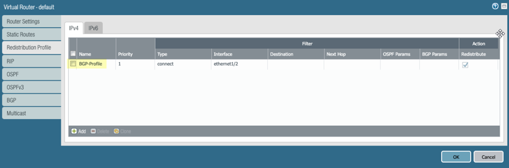
On the CPE in the remote network site, create static routes to the Prisma Access Service Endpoint Address and EBGP Router IP addresses you retrieved in a previous step.As previously stated, dynamic routing with BGP is required for this configuration. To facilitate BGP connection between the CPE and Prisma Access’ eBGP router, you need to add a static route for the eBGP router IP address on the CPE, and the next-hop must be the tunnel interface on the CPE. You must repeat this step for all other Remote Network eBGP router IP addresses on remaining tunnels.The following example shows the route on the active CPE. If you created backup tunnels on a standby CPE, create the same routing on the standby CPE.If you are configuring a Palo Alto Networks next-generation firewall, select to add the static routes.![]() Enable route redistribution on the CPE by selecting , then Add an IPv4 route redistribution profile.
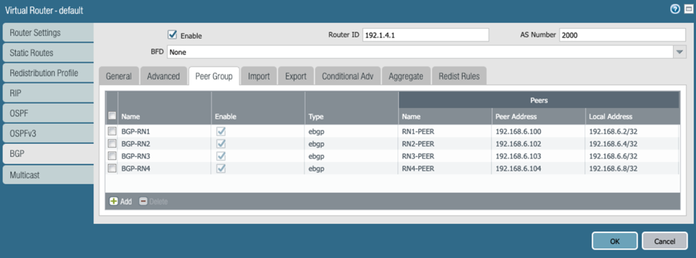
Enable route redistribution on the CPE by selecting , then Add an IPv4 route redistribution profile.![]() Select , Enable BGP on the virtual router instance, then Add Remote Network BGP peers.
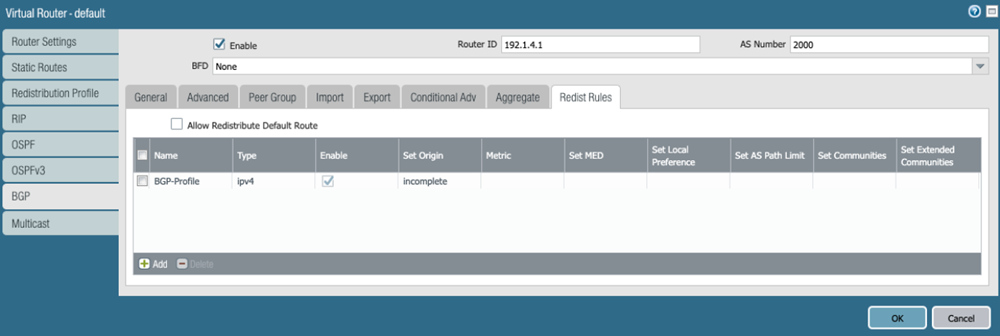
Select , Enable BGP on the virtual router instance, then Add Remote Network BGP peers.![]() Select , then attach the route redistribution profile you created in a previous step.
Select , then attach the route redistribution profile you created in a previous step.![]() Validate that the CPE is passing traffic on all four of its tunnels.Check the status of the ECMP-enabled connections from Prisma Access.
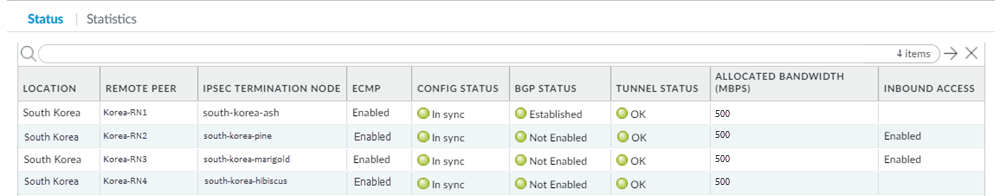
Validate that the CPE is passing traffic on all four of its tunnels.Check the status of the ECMP-enabled connections from Prisma Access.- Select , select the region where you deployed the ECMP connections, then select Status.
- In this area, ECMP displays as No. This is expected because you are not configuring the Prisma Access ECMP load balancing feature.
- ECMP is directional from CPE to Prisma Access and Prisma Access ensures symmetrical return of the traffic from the CPE.
![]()
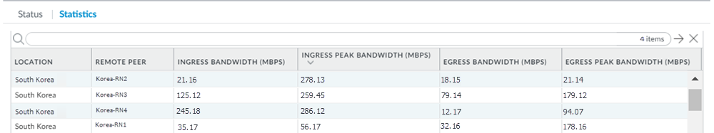
- Select Statistics to see that traffic is passing through each remote network tunnel.
![]()
When you have completed this workflow, you have created a high-bandwidth configuration for the remote network. Keep in mind that this solution is supported for outbound traffic only.