Configure 5G Multi-access Edge Computing Security
Table of Contents
Configure 5G Multi-access Edge Computing Security
Securing the network edge requires balancing
traffic inspection and control (security requirements) with high
bandwidth, low latency, and real-time access (user experience).
These issues are exponentially more difficult if traffic is processed
by many firewalls, if applications are hosted on edge sites, or
if the network edge is an aggregation point for IoT data. Additionally,
the separation of the user and the control plane in 5G networks
makes it difficult to apply security policy at the subscriber or
device level and lacks context-based visibility for threats.
5G
Multi-access Edge Computing Security provides granular visibility
and control for Packet Forwarding Control Protocol (PFCP) traffic
by extracting information (such as subscriber ID or equipment ID)
at the mobile edge, so you can apply security policy by subscriber,
by equipment, or by network slice. It provides security at the protocol
level through stateful inspection for PFCP traffic on 4G/LTE and
5G networks, in addition to reduced latency and higher bandwidth.
By
providing context-based visibility into threats, 5G Multi-access
Edge Computing Security protects networks from potential threats
such as vulnerabilities, malware, and viruses. It secures devices
and user that connect to multi-access edge computing (MEC), as well
as applications hosted on MEC from attacks such as Denial of Service
(DoS) and spoofing.
In 5G networks, PFCP carries control
traffic on the N4 interface between the SMF and UPF. It uses UDP
as a transport protocol and the reserved port number 8805. The PFCP
association between the SMF and the UPF is set up before the PFCP
sessions are established.
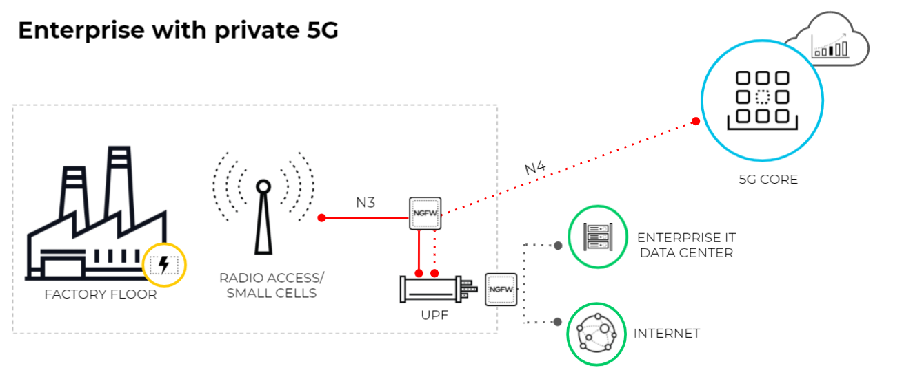
The following diagram illustrates
an enterprise that uses a private 5G network. The 5G core functions
are cloud-based or in the central site of the service provider.
The connection between the 5G access and the UPF uses the N3 interface.
The GTP-U tunnels carry the user plane traffic on the N3 interface.
The connection between the UPF and the Session Management Function
(SMF) uses the N4 interface. The PFCP protocol exchanges packet
forwarding rules using UDP exchanges on the N4 interface.
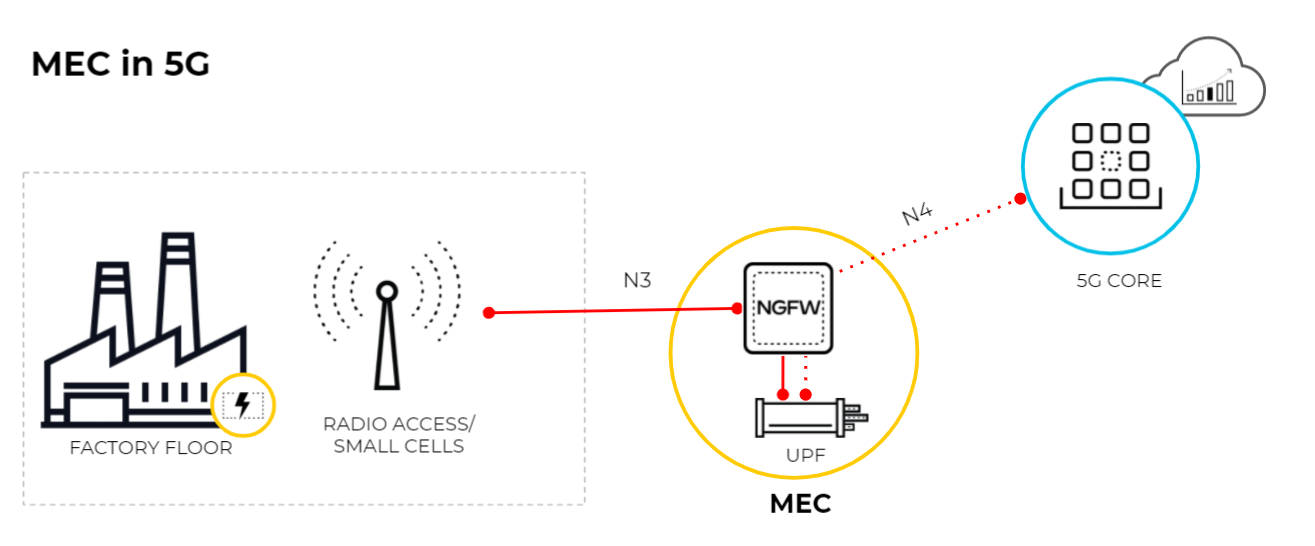
This diagram
illustrates MEC in a 5G network where the User Plane Function (UPF)
is at the edge or MEC location and the 5G core functions are cloud-based
or at the central site of the service provider. The connection between
the 5G access and the UPF uses the N3 interface and the GTP-U tunnels
carry the user plane traffic over the N3 interface. The connection between
UPF and the SMF uses the N4 interface and the PFCP protocol exchanges
packet forwarding rules using UDP over the N4 interface.
- Enable GTP Security, commit your changes, and reboot.If you enable stateful inspection for PFCP traffic, the following options are not available:
- IMSI/APN/RAT filtering
- GTP-U tunnel limiting
- GTPv1-C stateful inspection
- GTPv2-C stateful inspection
- 5G-HTTP2 for 5G-C
- End User IP Address Spoofing for GTP-U
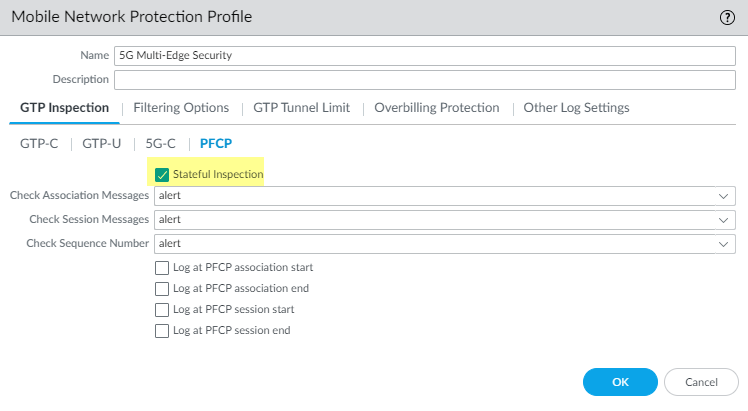
Create a Mobile Network Protection Profile and enable 5G Multi-access Edge Computing Security.- Select .Add a profile and enter a Name, such as 5G Multi-access Edge Computing Security.On the PFCP tab, enable Stateful Inspection.
![]() Select which state checks you want the firewall to perform on PFCP traffic and the action you want the firewall to take if a state check is not successful.
Select which state checks you want the firewall to perform on PFCP traffic and the action you want the firewall to take if a state check is not successful.- Determine the state checks you want to use.
- Check Association Messages—Checks for any PFCP association messages that are out of order or that have been rejected.
- Check Session Messages—Checks for any PFCP session messages that are out of order or that have been rejected; verifies that all PFCP session messages match an existing PFCP association; alerts or drops PFCP session messages that arrive before the PFCP association is set up.
- Check Sequence Number—Confirms that the sequence number in the PFCP response matches the sequence number in the preceding PFCP request message.
Select the action you want the firewall to take if a state check is not successful.- allow—Allow the traffic and do not generate a log entry in the GTP log.
- block—Block the traffic and generate a high-severity log entry in the GTP log.
- alert—(Default) Allow the traffic and generate a high-severity log entry in the GTP log.
(Optional) Configure logging for PFCP traffic.- Select when you want the firewall to generate a log entry.
- Log at PFCP association start
- Log at PFCP association end
- Log at PFCP session start
- Log at PFCP session end
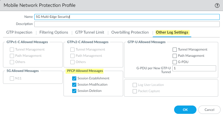
On the Other Log Settings tab, select the type of PFCP Allowed Messages you want to include in the logs.Enable these options for troubleshooting only.- Session Establishment—These PFCP messages set up the session, including establishing the GTP-U tunnel.
- Session Modification—These PFCP messages are sent if the session ID or PDR ID changes (for example, as a result of moving from a 4G to a 5G network. It includes messages such as PFCP Session Modification Request and PFCP Session Modification Response.
- Session Deletion—These PFCP messages terminate the PFCP session, including releasing associated resources.
![]() Click OK.Create a Security policy rule that applies your Mobile Network Protection profile to N4 PFCP traffic and N3 GTP-U traffic.
Click OK.Create a Security policy rule that applies your Mobile Network Protection profile to N4 PFCP traffic and N3 GTP-U traffic.- Select and Add a Security policy rule.For Source Address, Add the address objects for the 5G element endpoints on the N3 and N4 interfaces that you want to allow.For Destination, Add the Destination Address address objects for the 5G element endpoints on the N3 and N4 interfaces that you want to allow.Add the Applications to allow, such as gtp-u and pfcp.On the Actions tab, select the Action, such as Allow.Select the Mobile Network Protection profile you created.Create another Security policy rule based on equipment ID, subscriber ID, or network slice.
- Select and Add a Security policy rule.Specify the source criteria you want to use for this rule.
- Add one or more Source
Equipment IDs in any of the following formats (if you
configured an EDL, specify that EDL):
- 5G Permanent Equipment Identifier (PEI) including IMEI
- IMEI (15 or 16 digits)
- IMEI prefix of eight digits for Type Allocation Code (TAC)
- EDL that specifies IMEIs
- Select Source and Add one
or more Network Slices in either of the following
formats:
- Standardized SST (select eMBB, MIoT, or URLLC).
- Operator-specific SSTs in the format of text,number (number range is 128 to 255 in decimal).
- Add one or more Source Subscriber IDs
(if you configured an EDL, specify that EDL).
- 5G Subscriber Permanent Identifier (SUPI) including IMSI
- IMSI (14 or 15 digits)
- Range of IMSI values separated by a hyphen. In a range, only the 11th digit through the 15th digit of the IMSI can change from the start of the range to the end of the range; for example, 111111111111122-111111111119999.
- IMSI prefix of six digits with an asterisk (*) as the wildcard after the prefix; for example, 926789*.
- EDL that specifies IMSIs
Specify Source Zone, Source Address, Source User, and Source Device or use the default Any setting for each.Specify Destination Zone, Destination Address, and Destination Device or use the default Any setting for each.Add the Applications to allow, for example, youtube, facebook, linkedin, and twitter.On the Actions tab, select the Action, such as Allow.Commit your changes.