CN-Series
Configure Traffic Flow Towards CN-Series HSF
Table of Contents
Expand All
|
Collapse All
CN-Series Firewall Docs
-
- CN-Series System Requirements for the Kubernetes Cluster
- CN-Series System Requirements for On-Premises Kubernetes Deployments
- CN-Series Performance and Scaling
- Create Service Accounts for Cluster Authentication
- Get the Images and Files for the CN-Series Deployment
- Strata Logging Service with CN-Series Firewall
- IOT Security Support for CN-Series Firewall
- Software Cut-through Based Offload on CN-Series Firewall
-
HSF
- Deployment Modes
- HSF
- In-Cloud and On-Prem
-
- CN-Series HSF System Requirements
- Configure Traffic Flow Towards CN-Series HSF
- Test Case: Layer 3 BFD Based CN-GW Failure Handling
- View CN-Series HSF Summary and Monitoring
- Validating the CN-Series HSF Deployment
- Custom Metric Based HPA Using KEDA in EKS Environments
- Configure Dynamic Routing in CN-Series HSF
- Features Not Supported on the CN-Series
Configure Traffic Flow Towards CN-Series HSF
| Where Can I Use This? | What Do I Need? |
|---|---|
|
|
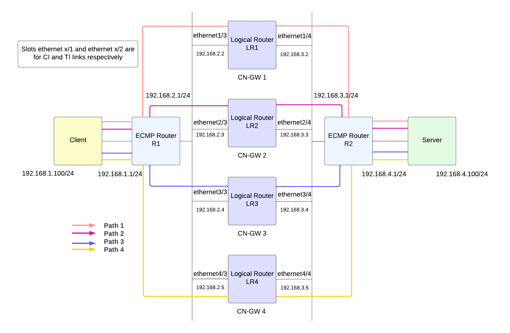
The upstream/downstream router uses flow-based ECMP algorithm. When traffic reaches
CN-GW, it will distribute the traffic to one of the available CN-NGFWs through the
Traffic Interconnect (TI) link using symmetric hash algorithm. Traffic matching a
session from both directions (client to server and server to client) will always go
through the same CN-NGFW. Once the CN-NGFW process the traffic, and if you have set
a policy to Allow traffic, the traffic packet will be sent
back to the CN-GW to reach the server.

- Create a Logical Router on the firewall to participate in Layer 3 routing.
- Go to NetworkRouting Logical Router then select the variable template from the Template drop-down.
- Select a default virtual router or add a Name for the new logical router.
- Select General, then add an already defined Interface.Repeat this step for adding all interfaces you want to add to the logical router.The ethernetX/1 and etehrnetX/2 interfaces are reserved for CI and TI links respectively. Select an interface between ethernet1/3 and ethernet1/14.
- Click OK.
- Set Administrative Distance for static routing. Range is 10 to 240; default is 10.Set Administrative Distances for types of routes as required for your network. When the virtual router has two or more different routes to the same destination, it uses administrative distance to choose the best path from different routing protocols and static routes by preferring a lower distance.
- Enable ECMP to leverage multiple equal-cost paths for forwarding.
- Click OK.
- Configure the Layer 3 interface to enable traffic flow.When you Prepare Panorama for CN-Series HSF Deployment, you might have created a variable Template. To enable traffic flow through the cluster network, you must configure the variable template with necessary network and traffic configuration needed for load balancing the CN-Series HSF. You must configure the Layer 3 Ethernet interface with IPv4 addresses so that the firewall can perform routing on these interfaces. You would typically use the following procedure to configure an external interface that connects to the internet and an interface for your internal network.You can configure this template before or after deploying the CN-Series HSF.Ensure to not overlap the configuration of this template with the K8S-CNF-Clustering-Readonly template created automatically during the Kubernetes plugin installation.
- Go to NetworkInterfaces, then select the variable template from the Template drop-down.
- Select Ethernet interface to Add Interface.
- Select a Slot between 1 and 30.
- Enter an Interface Name between ethernet1/3 and ethernet1/14.
- For Interface Type, select Layer 3.
- On the Config tab:
- For Logical Router, select the logical router you are configured in Step 1.
- For Virtual System, select the virtual system you are configuring if on a multi-virtual system firewall.
- For Security Zone, select the zone to which the interface belongs or create a New Zone.

- On the IPv4 tab, select DHCP Client.The firewall interface acts as a DHCP client and receives a dynamically assigned IP address. The firewall also provides the capability to propagate settings received by the DHCP client interface into a DHCP server operating on the firewall. For more information, see configure an interface as a DHCP client.
- Click OK.

- Configure static routes for the logical router.
- Go to NetworkRouting Logical Router, then select the variable template from the Template drop-down.
- Select the Static IPv4 tab and click Add.
- Enter a Name for the static route.
- Enter the Destination route and netmask. For example, 192.168.200.0/24.
- Select the outgoing interface for packets to use to go to the next hop.
- For Next Hop, select ip-address and enter the IP address of your internal gateway. For example, 192.168.100.2.
- Enter an Admin Distance for the route to override the default administrative distance set for static routes for this logical router (range is 10 to 240; default is 10).
- Enter a Metric for the route (range is 1 to 65,535).
- Apply a BFD Profile to the static route so that if the static route fails, the firewall removes the route and uses an alternative route. Default is None.
- Click OK.


