Connect DC Power to a PA-3400 Series Firewall
Table of Contents
Connect DC Power to a PA-3400 Series Firewall
Learn how to connect DC power to a PA-3400 Series firewall.
The following procedure describes how to connect DC power to a PA-3400 Series
firewall with DC power supplies.
You must swap the AC power supplies with DC power supplies
prior to performing this procedure.
Learn how to Set Up a Connection to the Firewall based on your desired boot mode prior
to powering on the firewall for the first time.
To avoid injury to yourself or damage to your Palo Alto Networks® hardware or the
data that resides on the hardware, read the Product Safety Warnings.
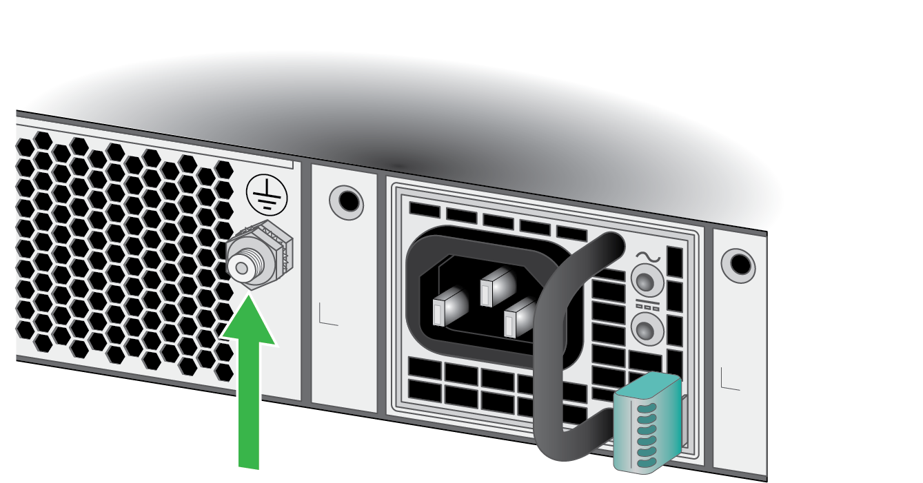
- Remove the nut and star washer from the ground stud on the back of the firewall.
![]() Crimp a 14AWG ground cable to a ring lug (cable and lug not included) and then attach the ring lug to the ground stud on the firewall. Replace the star washers and nuts and torque to 25 in-lbs. Connect the other end of the cable to earth ground.Power off the DC power sources that you will connect to the power supplies before you continue to the next step.Attach the DC power cables (not included) from the DC power source to the DC power supplies on the back of the firewall.
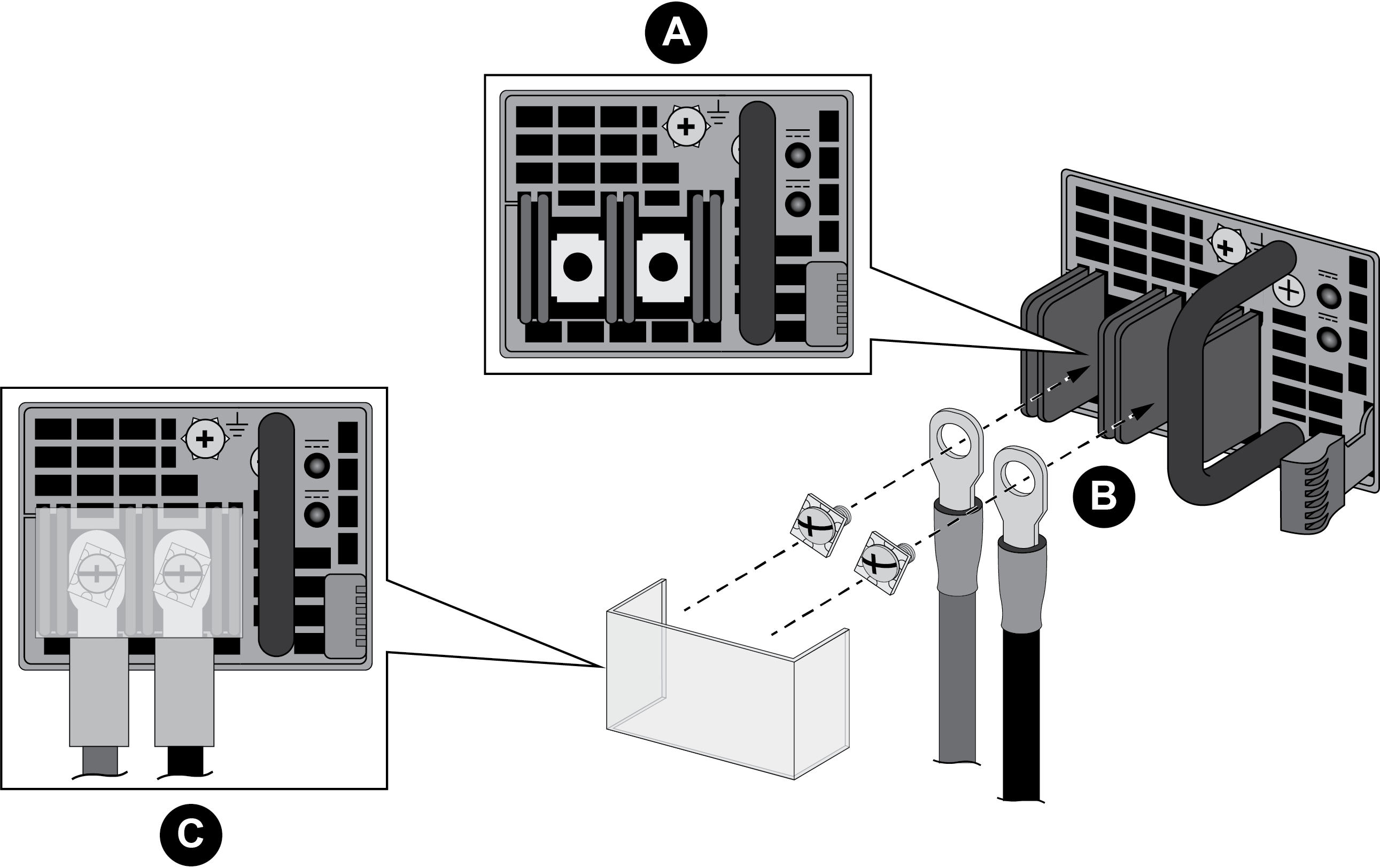
Crimp a 14AWG ground cable to a ring lug (cable and lug not included) and then attach the ring lug to the ground stud on the firewall. Replace the star washers and nuts and torque to 25 in-lbs. Connect the other end of the cable to earth ground.Power off the DC power sources that you will connect to the power supplies before you continue to the next step.Attach the DC power cables (not included) from the DC power source to the DC power supplies on the back of the firewall.- Remove the plastic DC power input cover from each of the two DC power supplies and then remove the positive and negative terminal screws.Crimp ring lugs to the ends of the positive and negative DC cables. These lugs are used to connect the DC cables to the DC inputs on the firewall.Use the DC terminal screws to connect a positive DC power cable to the positive terminal on the first DC power supply and then connect a negative DC power cable to the negative terminal. Repeat this step for the second DC power supply using separate positive and negative cables.Replace the plastic covers over each DC power input.Connect the two positive and two negative DC power cables to your power sources and ensure that you observe the correct polarity (positive to positive and negative to negative).Connect the second set of power cables through a different DC circuit to provide power redundancy and to allow for electrical circuit maintenance.
![]() After all DC power cables are securely connected, power on the DC power sources. The power supplies powers on, the input and output LEDs on the power supplies turn green, and the PWR LED and the power supply LEDs (PWR 1 and PWR 2) on the front of the firewall turns green.
After all DC power cables are securely connected, power on the DC power sources. The power supplies powers on, the input and output LEDs on the power supplies turn green, and the PWR LED and the power supply LEDs (PWR 1 and PWR 2) on the front of the firewall turns green.