Replace a Power Supply on a PA-5200 Series Firewall
Table of Contents
Replace a Power Supply on a PA-5200 Series Firewall
Learn how to replace a power supply on a PA-5200 Series
firewall.
PA-5200 Series firewalls have either two AC
or two DC power supplies (the second power supply is for redundancy).
If one power supply fails, you can replace it without service interruption
as described in the following procedures.
Replace an AC Power Supply on a PA-5200 Series Firewall
The following procedure describes how to replace
an AC power supply.
To avoid injury
to yourself or damage to your Palo Alto Networks® hardware or the
data that resides on the hardware, read the Product Safety Warnings.
- Identify the failed power supply by viewing the power supply LED on the back of the firewall; when there is a failure the FAIL LED turns solid yellow. For details on the power supply LEDS, see Interpret the LEDs on a PA-5200 Series Firewall.
- Remove the Velcro strap that secures the AC power cord to the power supply and remove the power cord.
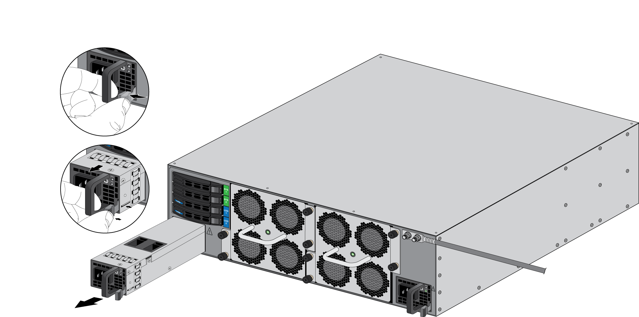
- Grasp the handle on the failed power supply and then
simultaneously press the release lever to the left and then pull
the power supply outward to remove it.
![]()
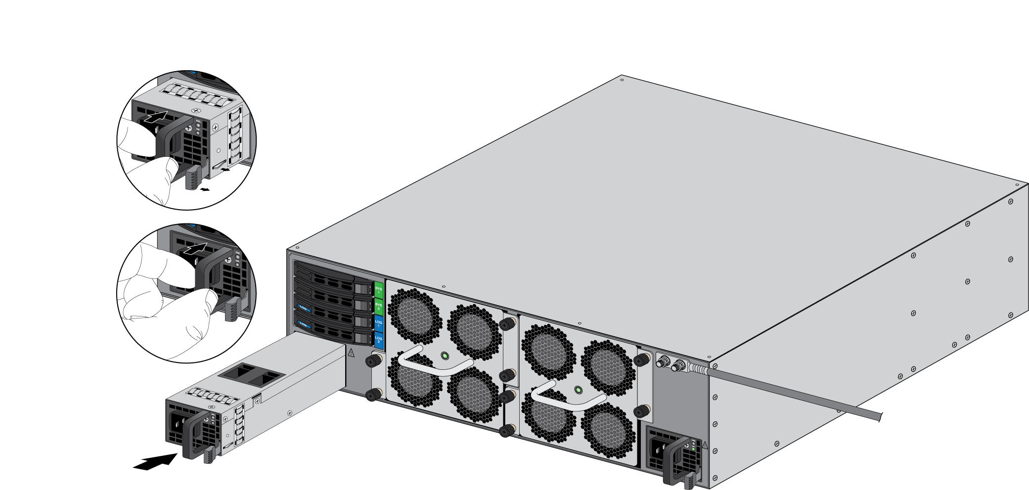
- Remove the replacement power supply from the packaging
and slide it into the empty power supply slot. Push the power supply
all the way in until the release lever clicks and secures the power
supply.
![]()
- Connect the AC power cord to the power supply input and
secure it to the power supply using the Velcro strap.
![]()
- Connect the other end of the power cord to a grounded AC power source. The new power supply automatically powers on, the OK LED turns green, the FAIL LED turns off, and the power LED (PWR 1 or PWR 2) on the front of the firewall turns green.

Replace a DC Power Supply on a PA-5200 Series Firewall
The following procedure describes how to replace
a DC power supply.
To avoid injury
to yourself or damage to your Palo Alto Networks® hardware or the
data that resides on the hardware, read the Product Safety Warnings.
- Identify the failed power supply by viewing the power supply LED on the back of the firewall; when there is a failure, the FAIL LED on the failed power supply turns solid yellow. For more details on the power supply LEDS, see Interpret the LEDs on a PA-5200 Series Firewall.
- Power off the DC power source that is connected to the
failed DC power supply.Ensure that the power is off before continuing to the next step.
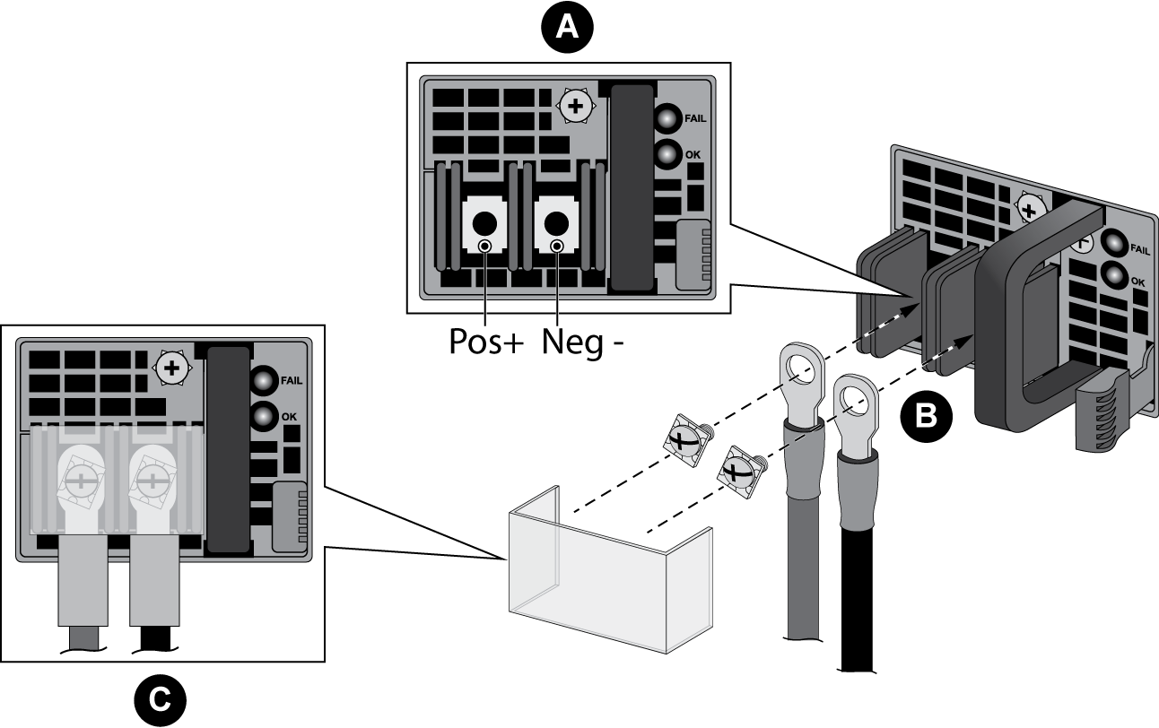
- Remove the plastic cover that protects the DC input terminals and
then use a Phillips-head screwdriver to remove the screws holding
the positive and negative DC cables to the DC input terminals.
![]()
- Grasp the handle on the failed power supply and then
simultaneously press the release lever to the left and pull the
power supply outward to remove it.
![]()
- Remove the replacement power supply from the packaging
and slide it into the empty power supply slot. Push the power supply
all the way in until the release lever clicks and secures the power
supply.
![]()
- Reconnect the positive and negative DC power cables to
the new power supply using the DC terminal screws.Make sure you establish the correct polarity: positive to positive and negative to negative.
![]()
- When all DC power cables are securely connected and the plastic guard is properly reattached, power on the DC power source.