Install the PA-5500 Series Firewall in an Equipment Rack
Table of Contents
Install the PA-5500 Series Firewall in an Equipment Rack
Learn how to install the PA-5500 Series Firewall in an equipment rack.
The following procedure describes how to install the PA-5540, PA-5550, PA-5560,
PA-5570, and PA-5580 firewalls in a 19” four-post equipment rack using the provided
four-post rack kit (PAN-PA-3RU-RACK-A). This kit is designed to provide additional
support for the back of the firewall.
The back panel of the firewall should remain accessible to ensure ease of
replacing a power supply or fan assembly.
Read the following safety information before you proceed with the equipment rack
installation:
- Elevated ambient operating temperature — If the PA-5500 Series firewall is installed in a closed or multi-unit rack assembly, the ambient operating temperature of the rack environment may be greater than the ambient room temperature. Verify that the ambient temperature of the rack assembly does not exceed the maximum rated ambient temperature requirements listed in the PA-5500 Series Firewall Environmental Specifications.
- Reduced airflow — Ensure that the airflow required for safe operation is not compromised by the rack installation.
- Mechanical loading — Ensure that the rack-mounted firewall does not cause hazardous conditions due to uneven mechanical loading.
- Circuit overloading — Ensure that the circuit that supplies power to the firewall is sufficiently rated to avoid circuit overloading or excess load on supply wiring. See PA-5500 Series Firewall Electrical Specifications.
- Reliable earthing — Maintain reliable earthing of rack-mounted equipment. Pay special attention to power connections other than direct connections to the branch circuit (such as use of power strips or extension cords) to ensure that the firewall does not exceed power ratings for connected hardware.
- Attach one fixed rack mount bracket to each side of the firewall. Use twelve #8-32 x 5/16” screws for the front six screw holes in each bracket. Use twelve #6-32 x 5/16” screws for the middle six screw holes in each bracket. Finally, use six #6-32 x 5/16" screws for the back screw holes in each bracket. Torque each screw to 15 in-lbs.
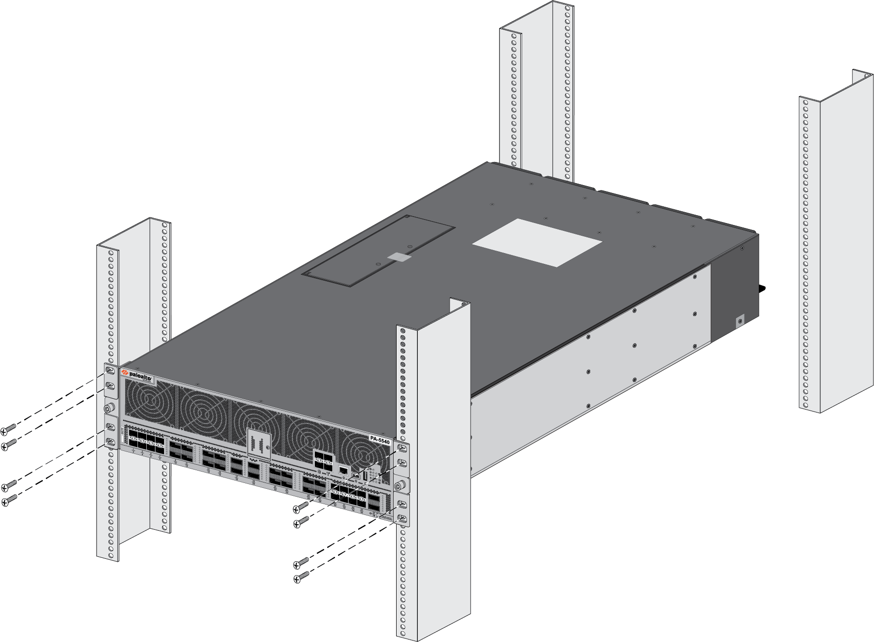
![]() With help from another person, hold the firewall in the rack and secure the fixed rack mount brackets to the front rack-posts using four screws for each bracket. Use the appropriate screws (#10-32 x 3/4” or #12-24 x 1/2”) for your rack and torque each screw to 25 in-lbs. Use the provided cage nuts to secure the screws if the rack has square holes.
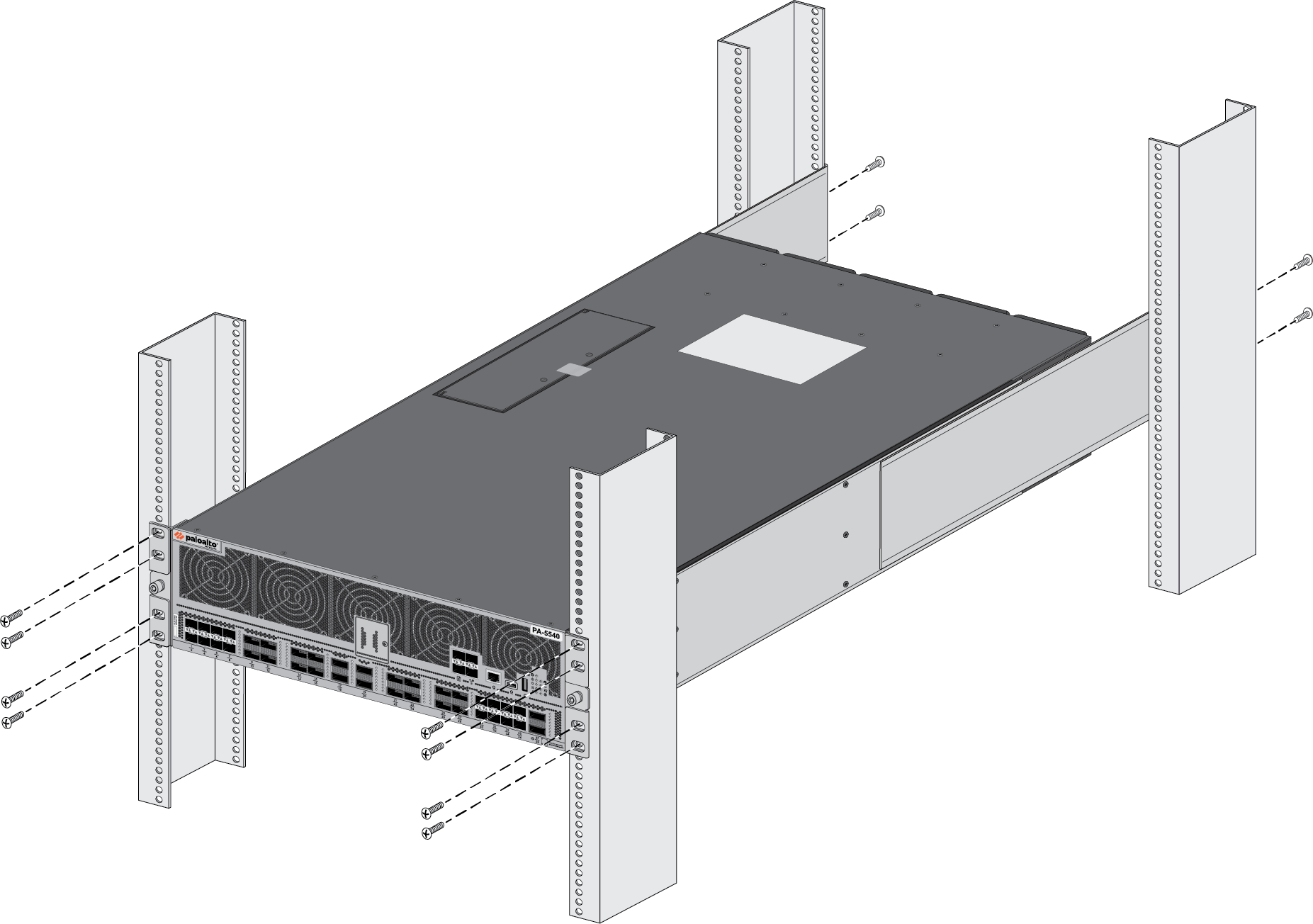
With help from another person, hold the firewall in the rack and secure the fixed rack mount brackets to the front rack-posts using four screws for each bracket. Use the appropriate screws (#10-32 x 3/4” or #12-24 x 1/2”) for your rack and torque each screw to 25 in-lbs. Use the provided cage nuts to secure the screws if the rack has square holes.![]() Slide one adjustable rack mount bracket into each of the two previously installed fixed rack mount bracket. Secure the two adjustable rack mount brackets to the back rack-posts using two screws for each bracket (#10-32 x 3/4” or #12-24 x 1/2” screws) and torque each screw to 25 in-lbs.
Slide one adjustable rack mount bracket into each of the two previously installed fixed rack mount bracket. Secure the two adjustable rack mount brackets to the back rack-posts using two screws for each bracket (#10-32 x 3/4” or #12-24 x 1/2” screws) and torque each screw to 25 in-lbs.![]()