WF-500-B Front Panel
Table of Contents
WF-500-B Front Panel
Learn about the front panel features of the WF-500-B
appliance.
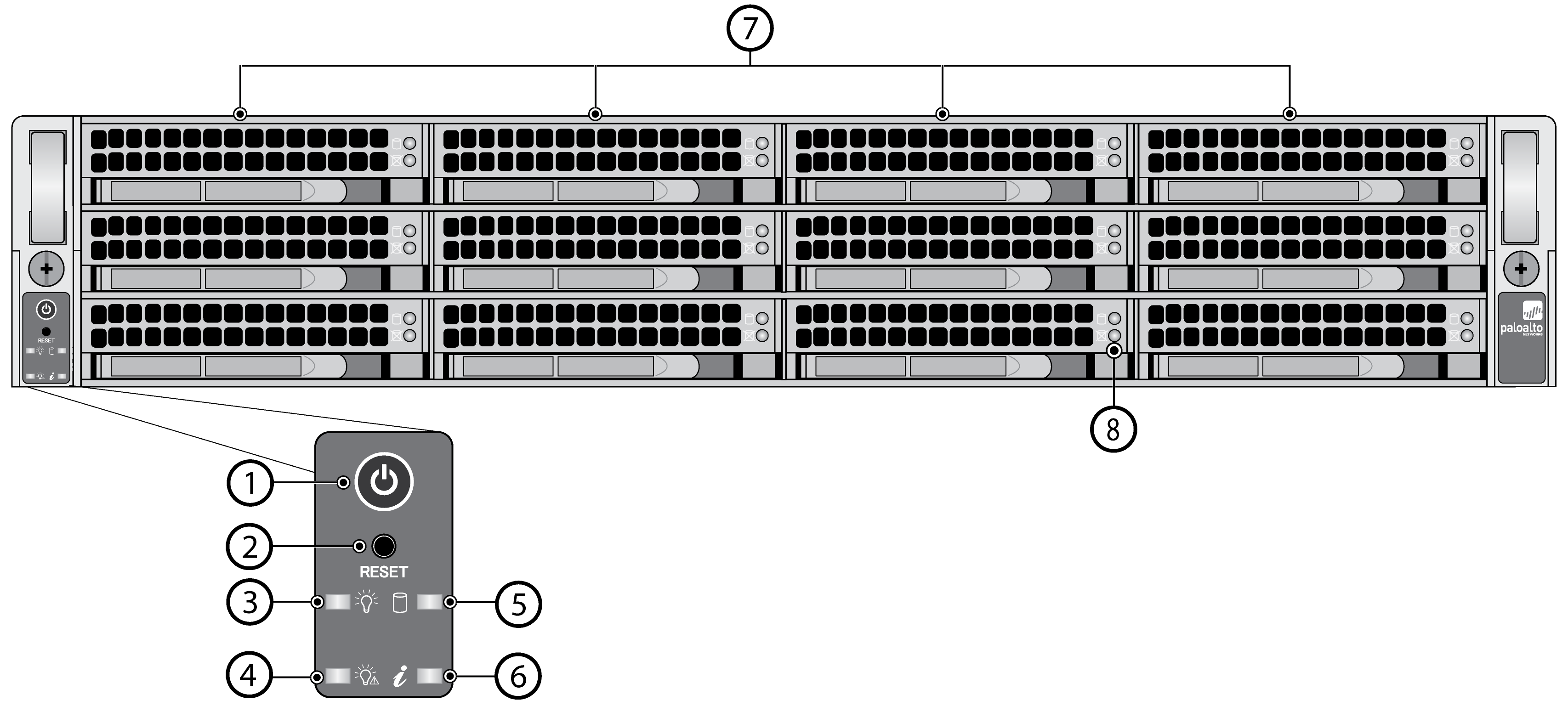
The following image shows the front panel
of the WF-500-B appliance and the table describes each front panel
component.
Item | Component | Description |
|---|---|---|
1 | Power button | Press this button to power on or power off
the appliance. Powering off the appliance with this button puts
the appliance in standby power mode. To completely power off the
appliance, you must disconnect the AC power cords from both power supplies. |
2 | Reset button |
Functions identically to the UID button on the M-300 Appliance Front
Panel.
Use the UID feature to help you locate the appliance when you move
from the front to the back of the equipment rack where the appliance
is installed. When you push the UID button to enable the UID
feature, both the front-panel System information LED and the
back-panel UID LED illuminate bright blue to help you locate the
appliance when you move between opposite sides of the equipment
rack. Push the UID button again to deactivate these LEDs.
|
3 | Power LED | Solid green indicates that the appliance
is powered on. |
4 | Power failure LED | Solid red indicates that either a power
supply failed or that there is no power source connected to a power
supply. |
5 | Hard-disk drive (HDD) LED | Blinking yellow indicates IDE channel activity (SAS/SATA
drive) on the front log drives. |
6 | System information (overheat and UID) LED |
|
7 | Hard-disk drives (HDDs) | Disk drive bays and HDDs used
for log storage. By default, the WF-500-B ships with four HDDs installed
in drive bays A1/A2 and B1/B2. You can install up to eight additional
drives (four additional RAID 1 pairs) in the remaining drive bays
(C1/C2, D1/D2, E1/E2, and F1-F2) to increase log storage capacity. Each
pair of drives are in a RAID 1 configuration. For example, A1-A2
is a RAID 1 pair and B1-B2 is a RAID 1 pair. |
8 | Hard-disk drive (HDD) LEDs | Status LEDs—two for each log drive:
|