Configure QoS for a Virtual System
Table of Contents
Configure QoS for a Virtual System
QoS can be configured for a single or several
virtual systems configured on a Palo Alto Networks firewall. Because
a virtual system is an independent firewall, QoS must be configured
independently for a single virtual system.
Configuring QoS
for a virtual system is similar to configuring QoS on a physical
firewall, with the exception that configuring QoS for a virtual
system requires specifying the source and destination of traffic.
Because a virtual system exists without set physical boundaries
and because traffic in a virtual environment spans more than one
virtual system, specifying source and destination zones and interfaces
for traffic is necessary to control and shape traffic for a single
virtual system.
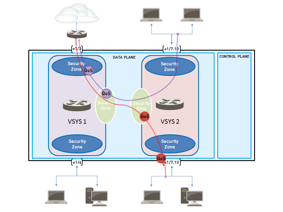
The example below shows two virtual systems
configured on firewall. VSYS 1 (purple) and VSYS 2 (red) each have
QoS configured to prioritize or limit two distinct traffic flows,
indicated by their corresponding purple (VSYS 1) and red (VSYS 2)
lines. The QoS nodes indicate the points at traffic is matched to
a QoS policy and assigned a QoS class of service, and then later
indicate the point at which traffic is shaped as it egresses the
firewall.
Refer
to Virtual
Systems for information on virtual systems and how to configure
them.
- Confirm that the appropriate interfaces, virtual routers, and security zones are associated with each virtual system.
- To view configured interfaces, select .
- To view configured zones, select .
- To view information on defined virtual routers, select .
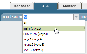
Identify traffic to apply QoS to.Select ACC to view the Application Command Center page. Use the settings and charts on the ACC page to view trends and traffic related to Applications, URL filtering, Threat Prevention, Data Filtering, and HIP Matches.To view information for a specific virtual system, select the virtual system from the Virtual System drop-down:![]() Click any application name to display detailed application information.Identify the egress interface for applications that you identified as needing QoS treatment.In a virtual system environment, QoS is applied to traffic on the traffic’s egress point on the virtual system. Depending the configuration and QoS policy for a virtual system, the egress point of QoS traffic could be associated with a physical interface or could be a zone.This example shows how to limit web-browsing traffic on vsys 1.Select to view traffic logs. Each entry has the option to display columns with information necessary to configure QoS in a virtual system environment:
Click any application name to display detailed application information.Identify the egress interface for applications that you identified as needing QoS treatment.In a virtual system environment, QoS is applied to traffic on the traffic’s egress point on the virtual system. Depending the configuration and QoS policy for a virtual system, the egress point of QoS traffic could be associated with a physical interface or could be a zone.This example shows how to limit web-browsing traffic on vsys 1.Select to view traffic logs. Each entry has the option to display columns with information necessary to configure QoS in a virtual system environment:- virtual system
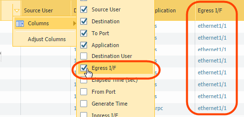
- egress interface
- ingress interface
- source zone
- destination zone
To display a column if it is not displayed by default:- Click any column header to add a column to the log:
![]()
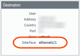
- Click the spyglass icon to the left of any entry to display a detailed log that includes the application’s egress interface, as well as source and destination zones, in the Source and Destination sections:
![]()
For example, for web-browsing traffic from VSYS 1, the ingress interface is ethernet 1/2, the egress interface is ethernet 1/1, the source zone is trust and the destination zone is untrust.Create a QoS Profile.You can edit any existing QoS Profile, including the default, by clicking the profile name.- Select and click Add to open the QoS Profile dialog.Enter a descriptive Profile Name.Enter an Egress Max to set the overall bandwidth allocation for the QoS profile.Enter an Egress Guaranteed to set the guaranteed bandwidth for the QoS profile.Any traffic that exceeds the QoS profile’s egress guaranteed limit is best effort but is not guaranteed.In the Classes section of the QoS Profile, specify how to treat up to eight individual QoS classes:
- Click Add to add a class to the QoS Profile.
- Select the Priority for the class.
- Enter an Egress Max for a class to set the overall bandwidth limit for that individual class.
- Enter an Egress Guaranteed for the class to set the guaranteed bandwidth for that individual class.
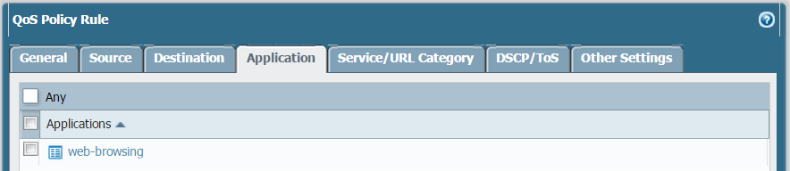
Click OK to save the QoS profile.Create a QoS policy.In an environment with multiple virtual systems, traffic spans more than one virtual system. Because of this, when you are enabling QoS for a virtual system, you must define traffic to receive QoS treatment based on source and destination zones. This ensures that the traffic is prioritized and shaped only for that virtual system (and not for other virtual systems through which the traffic might flow).- Select and Add a QoS Policy Rule.Select General and give the QoS Policy Rule a descriptive Name.Specify the traffic to which the QoS policy rule will apply. Use the Source, Destination, Application, and Service/URL Category tabs to define matching parameters for identifying traffic.For example, select Application and Add web-browsing to apply the QoS policy rule to that application:
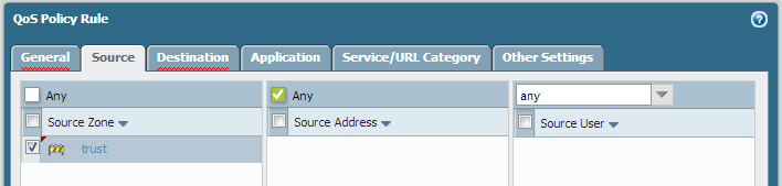
![]() Select Source and Add the source zone of vsys 1 web-browsing traffic.
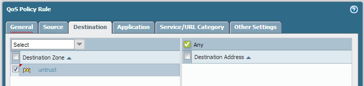
Select Source and Add the source zone of vsys 1 web-browsing traffic.![]() Select Destination and Add the destination zone of vsys 1 web-browsing traffic.
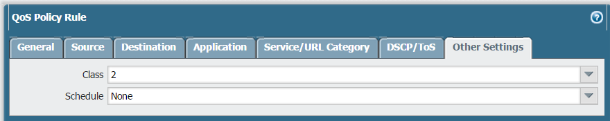
Select Destination and Add the destination zone of vsys 1 web-browsing traffic.![]() Select Other Settings and select a QoS Class to assign to the QoS policy rule. For example, assign Class 2 to web-browsing traffic on vsys 1:
Select Other Settings and select a QoS Class to assign to the QoS policy rule. For example, assign Class 2 to web-browsing traffic on vsys 1:![]() Click OK to save the QoS policy rule.Enable the QoS Profile on a physical interface.It is a best practice to always define the Egress Max value for a QoS interface.
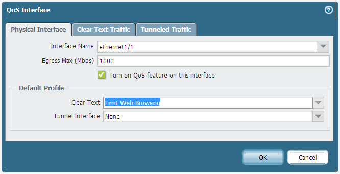
Click OK to save the QoS policy rule.Enable the QoS Profile on a physical interface.It is a best practice to always define the Egress Max value for a QoS interface.- Select and click Add to open the QoS Interface dialog.Enable QoS on the physical interface:
- On the Physical Interface tab, select the Interface Name of the interface to apply the QoS Profile to.In this example, ethernet 1/1 is the egress interface for web-browsing traffic on vsys 1 (see Step 2).
![]()
- Select Turn on QoS feature on this interface.
On the Physical Interface tab, select the default QoS profile to apply to all Clear Text traffic.(Optional) Use the Tunnel Interface field to apply a default QoS profile to all tunneled traffic.(Optional) On the Clear Text Traffic tab, configure additional QoS settings for clear text traffic:- Set the Egress Guaranteed and Egress Max bandwidths for clear text traffic.
- Click Add to apply a QoS Profile to selected clear text traffic, further selecting the traffic for QoS treatment according to source interface and source subnet (creating a QoS node).
(Optional) On the Tunneled Traffic tab, configure additional QoS settings for tunnel interfaces:- Set the Egress Guaranteed and Egress Max bandwidths for tunneled traffic.
- Click Add to associate a selected tunnel interface with a QoS Profile.
Click OK to save changes.Commit the changes.Verify QoS configuration.- Select to view the QoS Policies page. The QoS Policies page verifies that QoS is enabled and includes a Statistics link. Click the Statistics link to view QoS bandwidth, active sessions of a selected QoS node or class, and active applications for the selected QoS node or class.
- In a multi-vsys environment, sessions cannot span multiple systems. Multiple sessions are created for one traffic flow if the traffic passes through more than one virtual system. To browse sessions running on the firewall and view applied QoS Rules and QoS Classes, select .