SD-WAN
Define Your ISP Connections and Link Types
Table of Contents
Define Your ISP Connections and Link Types
Configure an SD-WAN interface profile to group physical links
by
the link tag and control link speeds.
| Where Can I Use This? | What Do I Need? |
|---|---|
|
|
Create an SD-WAN interface profile to define the characteristics of
ISP connections and to specify the speed of links and how frequently the firewall
monitors the link, and specify a link tag for the
link.
SD-WAN link tags group multiple links together that is called link
bundling or scaling.
Link tags are
used to identify common link types and links in SD-WAN interface
profiles. They are free form entries that are referenced in multiple locations. Be
consistent and meaningful when creating the link tags.
The tag enables you to control the order in which the interfaces are used and
systematically configure multiple interfaces with SD-WAN
functionality.
When you specify the same Link Tag on multiple links, you are
grouping (bundling) those physical links into a link bundle or fat pipe. You must
configure an SD-WAN interface profile and specify it for an Ethernet
interface enabled with SD-WAN before you can save the Ethernet
interface.
Group links based on a
Common
Criterion.
For example, group links by path preference from most preferred to least
preferred, or group links by cost.
SD-WAN interface profiles map tags to interfaces, and helps to set
bandwidths and probe rates. They also identify whether a transport is private (such
as MPLS), or public (such as Ethernet, ADSL, Cable).
PAN-OS & Panorama
Procedure to create SD-WAN interface profile in PAN-OS.
- Log in to the Panorama Web Interface.Select and select the appropriate template from the Template context drop-down.Add an SD-WAN interface profile.Enter a user-friendly Name for the SD-WAN interface profile, which you’ll see in reporting, troubleshooting, and statistics.Select the vsys Location if you have a multi-vsys Panorama™ management server. By default, vsys1 is selected.Select the Link Tag that this profile will assign to the interface.Add a Description for the profile.Select the physical Link Type from the predefined list (ADSL/DSL, Cable modem, Ethernet, Fiber, LTE/3G/4G/5G, MPLS, Microwave/Radio, Satellite, WiFi, Private Link1, Private Link2, Private Link3, Private Link4, or Other). (Beginning with PAN-OS 11.0.4, SD-WAN plugin 3.1.3 and later 3.1 releases) (PAN-OS 11.1.3, SD-WAN plugin 3.2.1 and later releases) We support the additional point-to-point private link types such as, Private Link1, Private Link2, Private Link3, and Private Link4. We do not support plain text traffic from SD-WAN branch firewall to SD-WAN hub firewall for Private Link1, Private Link2, Private Link3, and Private Link4 link types. When you configure any of the new private link types, ensure that you have an SD-WAN policy rule on the hub that is configured only with public link type. Because when the internet-bound traffic backhauls or fails to the hub from the branch, it must match with this SD-WAN policy rule. Otherwise, the traffic gets dropped as these private links (Private Link1, Private Link2, Private Link3, and Private Link4) are part of the direct internet access (DIA) SD-WAN interface.(For PAN-OS 11.0.4 and later releases, SD-WAN plugin 3.1.3 and later releases) To enable the additional point-to-point private link types, you must ensure the following:
- Panorama Management Server should be running on PAN-OS 11.0.4
- Panorama managed devices must be running on PAN-OS 11.0.4
- SD-WAN plugin version must be 3.1.3
(For PAN-OS 11.1.3 and later releases, SD-WAN plugin 3.2.1 and later releases) To enable the additional point-to-point private link types, you must ensure the following:- Panorama Management Server should be running on PAN-OS 11.1.3
- Panorama managed devices must be running on PAN-OS 11.1.3
- SD-WAN plugin version must be 3.2.1
(For PAN-OS 11.2.0 and later releases, SD-WAN plugin 3.3.0 and later releases ) To enable the additional point-to-point private link types, you must ensure the following:- Panorama Management Server should be running on PAN-OS 11.2.0
- Panorama managed devices must be running on PAN-OS 11.2.0
- SD-WAN plugin version must be 3.3.0
The firewall can support any CPE device that terminates and hands off as an Ethernet connection to the firewall; for example, WiFi access points, LTE modems, laser/microwave CPEs all can terminate with an Ethernet handoff.The following link types will form tunnels with only the same link type:- Public (or Other) link
types—Ethernet,
ASDL/DSL, Cable
modem, Fiber,
LTE/3G/4G/5G, WiFi, and
Other.Any public link type to any other public link type will create a tunnel successfully. For example, Ethernet-to-Other and Other-to-Other link types will create the tunnels successfully.
- Private and Point-to-Point link types—MPLS,
Satellite, Private
Link1, Private Link2,
Private Link3, Private
Link4, and
Microwave/Radio.A private link type can create the tunnel only with the same private link type. For example, MPLS-to-MPLS and satellite-to-satellite link types are valid and therefore the tunnels will be created successfully, but MPLS-to-satellite won't create the tunnel.
(SD-WAN plugin 2.0 and later versions) For existing PAN-OS deployments that have zones defined on the interfaces that will be used to support SD-WAN, Panorama may automatically configure the interface’s zone name to one of the predefined SD-WAN zones under the following conditions:- The SD-WAN interface is configured as a point-to-point private Link Type (MPLS, Satellite, or Microwave) in its Interface Profile.
- The VPN Data Tunnel Support checkbox is disabled (unchecked) on the SD-WAN Interface Profile. This instructs PAN-OS to forward traffic in clear text outside of the SD-WAN VPN tunnel. Because Private Link1, Private Link2, Private Link3, and Private Link4 link types don't support plain text traffic from SD-WAN branch firewall to SD-WAN hub firewall, you must leave VPN Data Tunnel Support option enabled when you configure these private link types.
(SD-WAN plugin 2.0 and later versions) On the Hub firewall, the zone name is configured as “zone-to-branch” when condition a) is met. On the Branch firewall, the zone name is configured as “zone-to-hub” when both condition a) and condition b) are met. Panorama automates this step to simplify configuration to ensure proper communication between the hub and branch firewalls. If you have preexisting firewall policies that reference the old zone name, you must update the policies to reflect the new predefined SD-WAN zone name.Specify the Maximum Download (Mbps) speed from the ISP in megabits per second (range is 0 to 100,000; there is no default). You can enter a range using up to three decimal places, for example, 10.456. Ask your ISP for the link speed or sample the link’s maximum speeds with a tool such as speedtest.net and take an average of the maximums over a good length of time.Specify the Maximum Upload (Mbps) speed to the ISP in megabits per second (range is 0 to 100,000; there is no default). You can enter a range using up to three decimal places, for example, 10.456. Ask your ISP for the link speed or sample the link’s maximum speeds with a tool such as speedtest.net and take an average of the maximums over a good length of time.(SD-WAN plugin 2.0 and later versions) Select Eligible for Error Correction Profile interface selection to enable Forward Error Correction (FEC) or packet duplication for interfaces. You must enable this on both the encoding and decoding firewalls; you must also create an error correction profile to apply to the SD-WAN policy rule for specific applications.(PAN-OS 9.1.2 and later versions) VPN Data Tunnel Support determines whether the branch-to-hub traffic and return traffic flows through a VPN tunnel for added security (the default method) or flows outside of the VPN tunnel to avoid encryption overhead.- Leave VPN Data Tunnel Support enabled for public link types that have direct internet connections or internet breakout capability, such as cable modem, ADSL, and other internet connections.
- You can disable VPN Data Tunnel Support for private link types such as MPLS, satellite, or microwave that do not have internet breakout capability except Private Link1, Private Link2, Private Link3, and Private Link4 link types. However, you must first ensure the traffic cannot be intercepted because it will be sent outside of the VPN tunnel.
- (SD-WAN plugin 3.1.3 and later releases) Because Private Link1, Private Link2, Private Link3, and Private Link4 link types don't support plain text traffic from SD-WAN branch firewall to SD-WAN hub firewall, you must leave VPN Data Tunnel Support enabled when you configure these private link types.
- The branch may have DIA traffic that needs to fail over to the private MPLS link connecting to the hub, and reach the internet from the hub. The VPN Data Tunnel Support setting determines whether the private data flows through the VPN tunnel or flows outside the tunnel, and the failed over traffic uses the other connection (that the private data flow doesn’t use). The firewall uses zones to segment DIA failover traffic from private MPLS traffic.
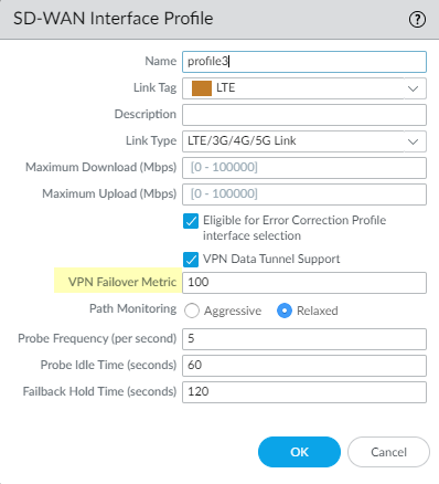
(PAN-OS 10.0.3 and later versions) If you configure DIA AnyPath, a principal virtual interface can have multiple hub virtual interfaces, so you must prioritize the order in which a particular hub is selected for failover. Specify such priority by setting the VPN Failover Metric for the VPN tunnels bundled in the hub virtual interface where this profile is applied. The lower the metric, the higher the priority of the interface to be selected during failover. If multiple hub virtual interfaces have the same metric value, SD-WAN sends new session traffic to them in round-robin fashion.![]() (Optional) Select the Path Monitoring mode in which the firewall monitors the interfaces where you apply this SD-WAN Interface Profile.The firewall selects what it considers the best monitoring method based on Link Type. Retain the default setting for the link type unless an interface (where you apply this profile) has issues that require more aggressive or more relaxed path monitoring.
(Optional) Select the Path Monitoring mode in which the firewall monitors the interfaces where you apply this SD-WAN Interface Profile.The firewall selects what it considers the best monitoring method based on Link Type. Retain the default setting for the link type unless an interface (where you apply this profile) has issues that require more aggressive or more relaxed path monitoring.- Aggressive—(Default for all link types except LTE and Satellite) Firewall sends probe packets to the opposite end of the SD-WAN link at a constant frequency. Use this mode if you need fast detection and failover for brownout and blackout conditions.
- Relaxed—(Default for LTE and Satellite link types) Firewall waits for a number of seconds (the Probe Idle Time) between sending sets of probe packets, making path monitoring less frequent. When the probe idle time expires, firewall sends probes for seven seconds at the Probe Frequency configured. Use this mode when you have low bandwidth links, links that charge by usage (such as LTE), or when fast detection isn’t as important as preserving cost and bandwidth.
Set the Probe Frequency (per second), which is the number of times per second that the firewall sends a probe packet to the opposite end of the SD-WAN link (range is 1 to 5; default is 5). The default setting provides subsecond detection of brownout and blackout conditions.If you change the Probe Frequency for a Panorama template, you should also adjust the Packet Loss percentage threshold in a Path Quality profile for a Panorama device group.If you select Relaxed path monitoring, you can set the Probe Idle Time (seconds) that the firewall waits between sets of probe packets (range is 1 to 60; default is 60).Enter the Failback Hold Time (seconds) that the firewall waits for a recovered link to remain qualified before the firewall reinstates that link as the preferred link after it has failed over (range is 20 to 120; default is 120).Click OK to save the profile.Commit and Commit and Push your configuration changes.Monitor your application and link path health metrics, and generate reports of your application and link health performance. For more information, see monitoring and reporting.Strata Cloud Manager
Procedure to create SD-WAN interface profile in Strata Cloud Manager.- Log in to Strata Cloud Manager.Select and select the hub or branch folder where want to create the SD-WAN interface profile.Add Profile.Enter a descriptive Name for the profile.Select the Link Tag the profile assigns to the interface.Select the Link Type from the predefined list.Specify the Maximum Download (Mbps) speed from the ISP.Specify the Maximum Upload (Mbps) speed to the ISP.Check (enable Eligible for Error Correction Profile Interface Selection to enable Forward Error Correction (FEC) or packet duplication for interfaces.If enabled, you must enable this setting for both sending and receiving firewalls.VPN Data Tunnel Support determines whether the branch-to-hub traffic and return traffic flows through a VPN tunnel for added security or flows outside of the VPN tunnel to avoid encryption overhead. This setting is enabled by default.
- Keep enabled for public links that have direct internet connections or internet break capabilities, such as cable modem, ADSL, and other internet connections.
- Disable for private link types such as MPLS, satellite, or microwave that doesn’t have internet breakout capability. However, you must first ensure that the traffic can’t be intercepted because it will be sent outside of the VPN tunnel.
- The branch might have DIA traffic that needs to fail over to the private MPLS link connecting to the hub, and reach the internet from the hub. The VPN Data Tunnel Support setting determines whether the private data flows through the VPN tunnel or flows outside the tunnel, and the failed over traffic uses the other connection (that the private data flow doesn’t use). The firewall uses zones to segment DIA failover traffic from private MPLS traffic.
Set the VPN Failover Metric if DIA AnyPath is enabled a hub or branch firewall, to prioritize the order in which a particular hub is selected for failover.The lower the metric, the higher the priority of the interface to be selected during failover. If multiple hub virtual interfaces have the same metric value, SD-WAN sends new session traffic to them in round-robin fashion.Select the Path Monitoring mode.- Aggressive—Firewall sends probe packets to the opposite end of the SD-WAN link at a constant frequency. Use this mode if you need fast detection and failover for brownout and blackout conditions. Default for all link types except LTE and Satellite.
- Relaxed—Firewall waits for a number of seconds (Probe Idle Time) between sending sets of probe packets, making path monitoring less frequent. When the probe idle time expires, firewall sends probes for 7 seconds at the Probe Frequency configured. Use this mode when you have low-bandwidth links, links that charge by usage (such as LTE), or when fast detection isn’t as important as preserving cost and bandwidth. Default for LTE and Satellite link types.
Set the Probe Frequency (per second) to specify the number of times per second the firewall sends a probe packet to the opposite end of the SD-WAN link. The default setting provides subsecond detection of brownout and blackout conditions.Set the Probe Idle Time (seconds) to specify how long the firewall waits between sets of probe packets.Set the Failback Hold Time (seconds) to specify how long the firewall waits for a recovered link to remain qualified before the firewall reinstates the link after it has failed.Save.