ION 5200 Front Panel
Table of Contents
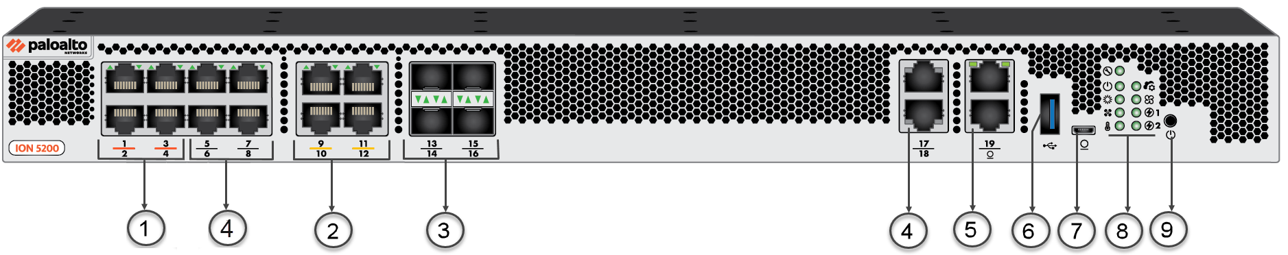
ION 5200 Front Panel
Learn the ION 5200 device front panel parts.
The following table describes the front
panel components of the ION 5200.
| Item | Component | Description |
|---|---|---|
| 1 | Bypass Pair | Ports 1 - 4 are Bypass pairs, 4 x 1G RJ45. |
| 2 | PoE Ports | Ports 9 - 12 are PoE MGig ports capable of 1G/2.5G. |
| 3 | SFP+ ports | Ports 13 - 16 are SFP+ (10G) ports and also supports 1G SFP. |
| 4 | RJ-45 Ports | Ports 5 - 8, 17-19 are RJ-45 10M/100M/1000M ethernet ports. |
| 5 | Console Port | RJ-45 Serial console port. Use this port to connect a management computer to the device using a 9-pin serial-to-RJ-45 cable. |
| 6 | Standard USB | USB Port. A USB port that accepts a USB flash drive. |
| 7 | Micro USB Port | Micro USB Console Port. Use this port to connect a management computer to the device using a standard Type-A USB-to-micro USB cable. |
| 8 | LED Indicators | LEDs indicate the status of the ION device components. |
| 9 | Power/Reset | Power LED; the LED turns green when powered on. |