Learn how to connect power to the PA-5500 Series Firewall.
The following procedure describes how to connect power to a PA-5540, PA-5550,
PA-5560, PA-5570, and PA-5580 firewall with either AC or DC power supplies
installed.
The AC and DC power supplies support two ranges of voltages: low line (90V to 140V)
and high line (180V to 260V). The input voltage range determines the number of power
supplies needed for the appliance. An appliance with low line input voltage requires
a minimum of three power supplies while an appliance with high line input voltage
requires a minimum of two power supplies. Any additional installed power supplies
provided redundancy.
Put the provided ESD wrist strap on your wrist ensuring that the metal contact
is touching your skin. Then attach (snap) one end of the ground cable to the
wrist strap and remove the alligator clip from the banana clip on the other end
of the ESD grounding cable. Plug the banana clip end into the ESD port located
on the back of the appliance before handling ESD sensitive hardware. For details
on the ESD port location, see PA-5500 Series Firewall Back Panel.
Ensure that your power source(s) are powered off.
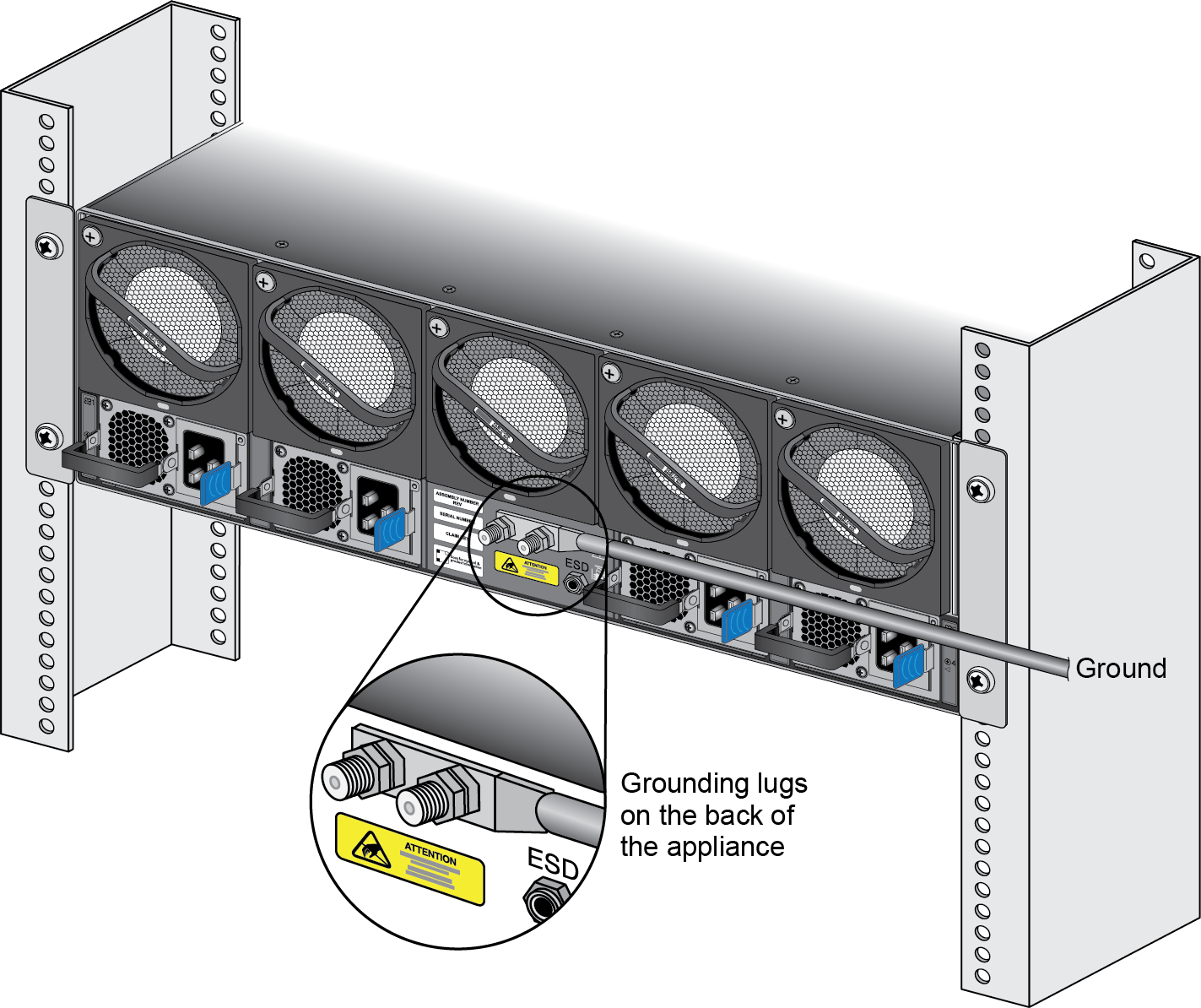
Remove the nuts from one of the ground studs located on the back of the
appliance.
Crimp a 6-AWG wire to the provided grounding lug and connect the other end to
your earth ground point.
Connect the lug connector to the ground stud on the appliance using the
provided nuts and torque the nut to 50 in-lbs. Be careful not to strip the nut
and lug stud.
Slide the AC or DC power supplies into the power supply slot(s).
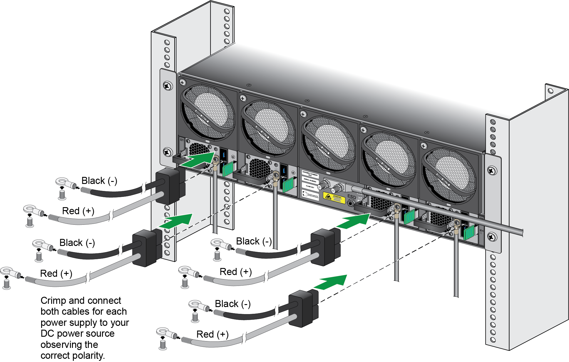
(DC Power Supplies only) Connect each DC power supply to a ground
connection.
Connect the power supplies to a power source based on whether your power
supplies are AC or DC.
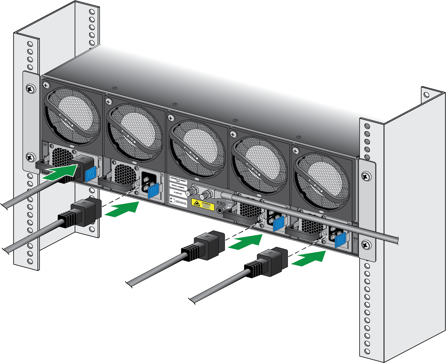
(AC Power Supplies)
Connect the first two power supplies to a 120VAC 15-amp circuit breaker
or 240VAC 20-amp circuit breaker using the provided power cords and then
connect the second two power supplies to a second, independent 120VAC
15-amp circuit breaker or 240VAC 20-amp circuit breaker.
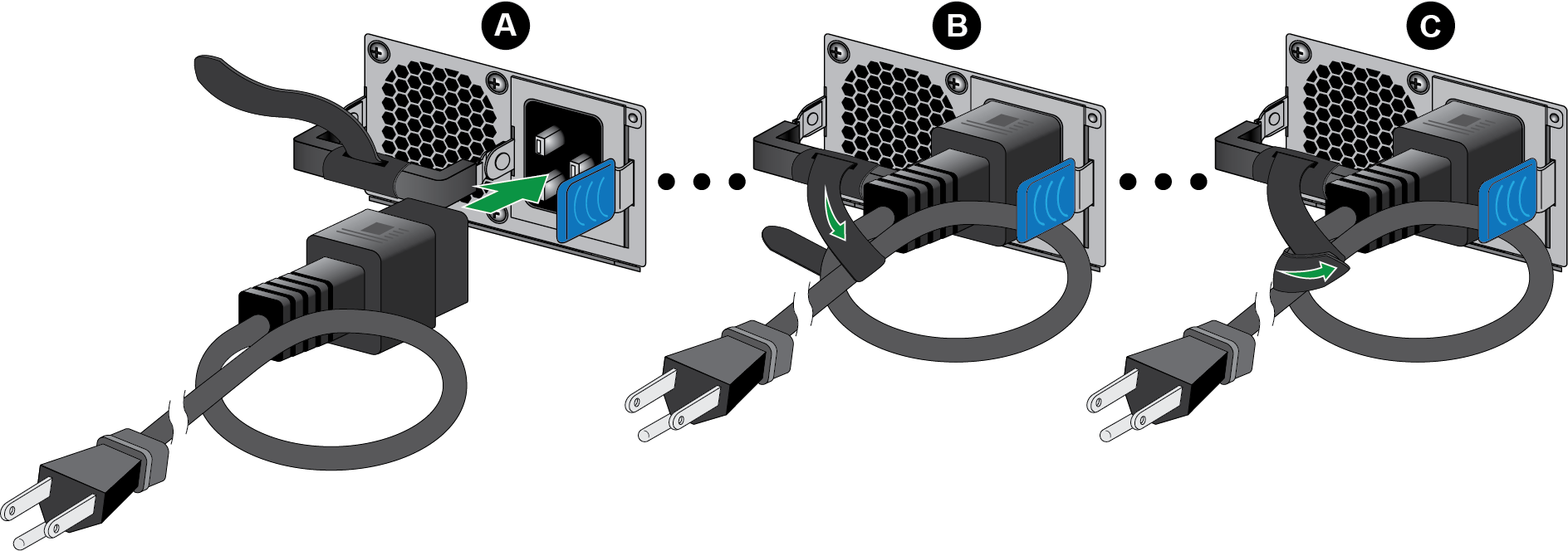
Secure the power cords to the power inlets using the velcro
straps.
(DC Power Supplies)
Connect the positive and negative cable ends into the respective
polarity slots in the connector, then plug the connector end into the
slot in the power supply. Repeat this for each power supply.
Connect the opposite end of the positive and negative cables to a 60A
circuit breaker, then secure the power cords to the power inlets using
the velcro straps.. Repeat this for each of the four power supplies,
ensuring that each power supply is connected to its own 60A power
circuit breaker. This ensures power redundancy and allows for planned
electrical circuit maintenance.
When cabling the DC power supply to your power source, ensure
that you route the cable in such a way that it does not put
pressure on the plastic clips located at the front of the DC
power supplies. It is best to route the cables first and then
plug the cables into the power supplies.
After each AC or DC cable is securely connected, turn on the power source and
the appliance will power on.
Before powering on the firewall, ensure that you have connected your
Ethernet cables in accordance to the mode you wish to boot the firewall
in (standard mode or Zero Touch Provisioning mode) as specified in Set Up a Connection to the Firewall.