Advanced Route Engine
Table of Contents
Advanced Route Engine
PAN-OS supports an advanced route engine for BGP and
static routing.
PAN-OS® provides an advanced route engine
that allows the firewall to scale and provide stable, high-performing,
and highly available routing functions to large data centers, ISPs,
enterprises, and cloud users. The advanced route engine supports
only BGP and static routing. The advanced route engine offering
is in preview mode for PAN-OS 10.0 and the next few releases as
Palo Alto Networks adds more routing protocols and more features within
BGP. In PAN-OS 10.0, the advanced route engine supports the basic
BGP features. View Features Not Supported on Advanced Route Engine.
Non-supported features are not carried over
from the legacy route engine to the advanced route engine (whether
BGP features, static route features, or unrelated features). You
should not enable the advanced route engine until you know that
all the features you require are supported.
Firewalls
using the advanced route engine are appropriate for large data centers,
enterprises, ISPs, and cloud services. The following models support
the advanced route engine:
- PA-7000 Series firewalls
- PA-5200 Series firewalls
- PA-3200 Series firewalls
- VM-Series firewalls
Although a supported firewall
can have a configuration that uses the legacy route engine and a
configuration that uses the advanced route engine, only one route
engine is in effect at a time. Each time you change the engine that
the firewall will use (enable or disable Advanced Routing to access
the advanced engine or legacy engine, respectively), you must commit
the configuration and reboot the firewall for the change to take
effect.
Before you switch to the advanced
route engine, make a backup of your current configuration.
Similarly,
if you configure Panorama with a template that enables or disables Advanced
Routing, after you commit and push the template to devices, you
must reboot the devices in the template for the change to take effect.
When configuring Panorama, create device
groups and Templates for devices that all use the same Advanced
Routing setting (all enabled or all disabled). Panorama won’t push
configurations with Advanced Routing enabled to smaller firewalls
that don’t support Advanced Routing. For those firewalls, Panorama
will push a legacy configuration if one is present.
The
advanced route engine supports only one logical router (known as
a virtual router on the legacy route engine). The advanced route
engine has more convenient menu options and there are more BGP settings
that you can easily configure in a profile (authentication, timers,
address family, or redistribution profile) that applies to a BGP
peer group or peer, for example.
- Make a backup of your current configuration before you enable the advanced route engine.Enable the advanced route engine.
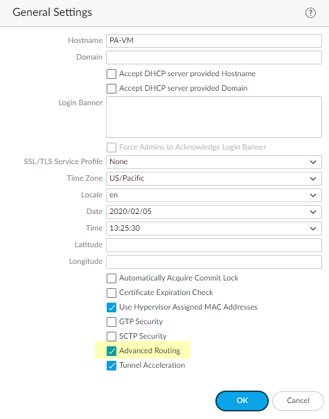
- Select and edit the General Settings.Enable Advanced Routing.
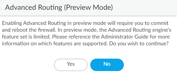
![]() Before you click OK, make sure you have made a backup of your configuration for the legacy route engine.Click OK.A message about preview mode appears; click Yes to proceed.
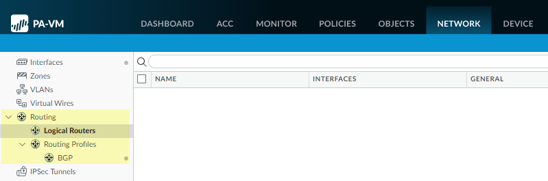
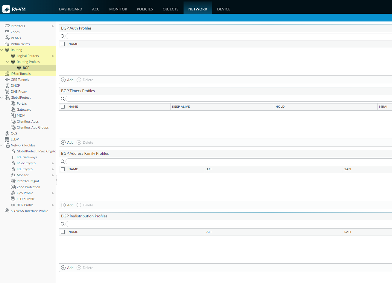
Before you click OK, make sure you have made a backup of your configuration for the legacy route engine.Click OK.A message about preview mode appears; click Yes to proceed.![]() Commit.Select and Reboot Device.Log back into the firewall.Select Network.Notice the updated menu items, which are more industry-standard and more detailed than the single item (Virtual Routers) on the legacy menu. Routing includes Logical Routers and Routing Profiles, which include BGP. Logical routers in the advanced route engine are equivalent to virtual routers in the legacy route engine.
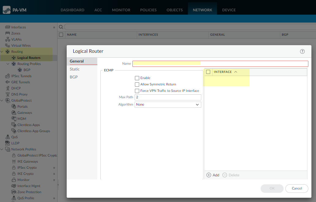
Commit.Select and Reboot Device.Log back into the firewall.Select Network.Notice the updated menu items, which are more industry-standard and more detailed than the single item (Virtual Routers) on the legacy menu. Routing includes Logical Routers and Routing Profiles, which include BGP. Logical routers in the advanced route engine are equivalent to virtual routers in the legacy route engine.![]() Select Interfaces and configure one or more Layer 3 Interfaces with a static IP address or Configure an Interface as a DHCP Client.Name the logical router and add interfaces to it.
Select Interfaces and configure one or more Layer 3 Interfaces with a static IP address or Configure an Interface as a DHCP Client.Name the logical router and add interfaces to it.- Select and Add the Name of the logical router.Add a Layer 3 Interface that you defined to the logical router.
![]() Click OK to save the logical router.Configure a static route.
Click OK to save the logical router.Configure a static route.- Select and select the logical router.Select Static and Add an IP or IPv6 static route by Name.For Destination, enter the route and netmask (for example, 192.168.2.2/24 for an IPv4 address or 2001:db8:123:1::1/64 for an IPv6 address). If you’re creating a default route, enter the default route (0.0.0.0/0 for an IPv4 address or ::/0 for an IPv6 address). Alternatively, you can create an address object of type IP Netmask.(Optional) For Interface, specify the outgoing interface for packets to use to go to the next hop. Specify an interface for stricter control over which interface the firewall uses rather than using the interface in the route table for the next hop of this route.For Next Hop, select one of the following:
- IP Address—Enter the IP address (for example, 192.168.56.1 or 2001:db8:49e:1::1) when you want to route to a specific next hop. You must Enable IPv6 on the interface (when you Configure Layer 3 Interfaces) to use an IPv6 next hop address. If you’re creating a default route, for Next Hop you must select IP Address and enter the IP address for your internet gateway (for example, 192.168.56.1 or 2001:db8:49e:1::1). Alternatively, you can create an address object of type IP Netmask. The address object must have a netmask of /32 for IPv4 or /128 for IPv6.
- Discard—Select to drop packets that are addressed to this destination.
- None—Select if there is no next hop for the route. For example, a point-to-point connection does not require a next hop because there is only one way for packets to go.
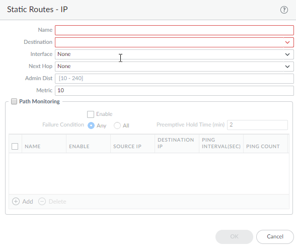
Enter the Admin Dist (administrative distance) for the route (range is 10 to 240; default is 10).Enter a Metric for the route (range is 1 to 65,535; default is 10).![]() Configure path monitoring for the static route; you can monitor up to 128 static routes.
Configure path monitoring for the static route; you can monitor up to 128 static routes.- Select Path Monitoring and Enable.Failure Condition determines whether path monitoring for the static route is based on one (any) or all monitored destinations. Select whether Any or All of the monitored destinations for the static route must be unreachable by ICMP for the firewall to remove the static route from the RIB and FIB and add the static route that has the next lowest metric (going to the same destination) to the FiB.Select All to avoid the possibility of any single monitored destination signaling a route failure when the destination is simply offline for maintenance, for example.(Optional) Specify the Preemptive Hold Time (min), the number of minutes a downed path monitor must remain in Up state before the firewall reinstalls the static route into the RIB; range is 0 to 1,440; default is 2. A setting of 0 (zero) causes the firewall to reinstall the route into the RIB immediately upon the path monitor coming up.The path monitor evaluates all of its monitored destinations for the static route and comes up based on the Any or All failure condition. If a link goes down or flaps during the hold time, when the link comes back up, the path monitor resumes and the Preemptive Hold Time is reset, causing the timer to restart from zero.Add a path monitoring destination by Name.Enable the path monitoring destination.For Source IP, select the IP address that the firewall uses in the ICMP ping to the monitored destination:
- If an interface has multiple IP addresses, select one.
- If you select an interface, the firewall uses the first IP address assigned to the interface by default.
- If you select DHCP (Use DHCP Client address), the firewall uses the address that DHCP assigned to the interface. To see the DHCP address, select and in the row for the Ethernet interface, click on Dynamic DHCP Client. The IP Address displays in the Dynamic IP Interface Status window.
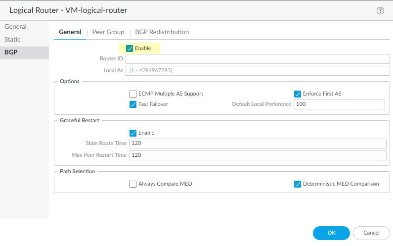
For Destination IP, enter an IP address or address object to which the firewall will monitor the path. The monitored destination and static route destination must use the same address family (IPv4 or IPv6).The destination IP address should belong to a reliable endpoint; you shouldn’t base path monitoring on a device that itself is unstable or unreliable.(Optional) Specify the ICMP Ping Interval (sec) in seconds to determine how frequently the firewall monitors the path (range is 1 to 60; default is 3).(Optional) Specify the ICMP Ping Count of packets that don’t return from the destination before the firewall considers the static route down and removes it from the RIB and FIB (range is 3 to 10; default is 5).Click OK to save the path monitor destination.Click OK twice to save the static route.Configure general BGP routing options.- Select and select the logical router.Select and Enable BGP.Assign a Router ID to BGP for the logical router, which is typically an IPv4 address to ensure the Router ID is unique.Assign the Local AS (autonomous system) to which the logical router belongs based on the Router ID (range for a 2-byte or 4-byte AS number is 1 to 4,294,967,295).
![]() Enable ECMP Multiple AS Support if you configured ECMP and you want to run ECMP over multiple BGP autonomous systems.Enforce First AS (enabled by default) to cause the firewall to drop an incoming Update message from an EBGP peer that does not list the EBGP peer’s own AS number as the first AS number in the AS_PATH attribute.Fast Failover of EBGP is enabled by default. You can disable EBGP fast failover if it causes the firewall to unnecessarily withdraw BGP routes.Specify the Default Local Preference that can be used to determine preferences among different paths; range is 0 to 4,294,967,295; default is 100.Enable Graceful Restart and configure the following timers:
Enable ECMP Multiple AS Support if you configured ECMP and you want to run ECMP over multiple BGP autonomous systems.Enforce First AS (enabled by default) to cause the firewall to drop an incoming Update message from an EBGP peer that does not list the EBGP peer’s own AS number as the first AS number in the AS_PATH attribute.Fast Failover of EBGP is enabled by default. You can disable EBGP fast failover if it causes the firewall to unnecessarily withdraw BGP routes.Specify the Default Local Preference that can be used to determine preferences among different paths; range is 0 to 4,294,967,295; default is 100.Enable Graceful Restart and configure the following timers:- Stale Route Time—Specify the length of time, in seconds, that a route can stay in the stale state (range is 1 to 3,600; default is 120).
- Max Peer Restart Time—Specify the maximum length of time, in seconds, that the local device accepts as a grace period restart time for peer devices (range is 1 to 3,600; default is 120).
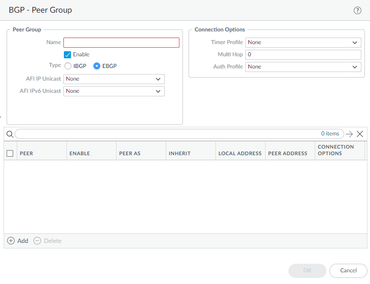
For Path Selection, enable Always Compare MED to choose paths from neighbors in different autonomous systems; default is disabled. The Multi-Exit Discriminator (MED) is an external metric that lets neighbors know about the preferred path into an AS. A lower value is preferred over a higher value.Enable the Deterministic MED Comparison to choose between routes that are advertised by IBGP peers (BGP peers in the same AS). Default is enabled.Click OK to save general BGP settings.Configure a BGP peer group.- Select and select the logical router.Select and Add a peer group by Name.Enable the peer group.Specify the peer group Type as IBGP (Internal BGP—peering within an AS) or EBGP (External BGP—peering between two autonomous systems).For AFI IP Unicast, select or create an AFI Profile (Create a BGP Address Family Identifier profile) to apply the settings in the profile to the peer group. The default is None.For AFI IPv6 Unicast, select or create an AFI Profile (Create a BGP Address Family Identifier profile) to apply the settings in the profile to the peer group. The default is None.
![]() Configure Connection Options:
Configure Connection Options:- Select or create a Timer Profile (Timers Profile) to apply to the peer group; default is None.
- For Multi Hop, set the time-to-live (TTL) value in the IP header; range is 1 to 255; default is 0. For EBGP, the default value of 0 means 1. For IBGP, the default value of 0 means 255.
- Select or create an Auth Profile (BGP Auth Profile) to authenticate BGP peer communications; default is None.
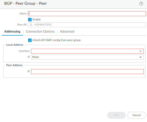
Add a BGP peer to the peer group.- Add a peer by Name and Enable the peer.Enter the Peer AS (autonomous system) to which the peer belongs; range is 1 to 4,294,967,295.Select Addressing.Select Inherit AFI/SAFI config from peer-group or select or create an AFI IP Unicast profile or an AFI IPv6 Unicast profile (Create a BGP Address Family Identifier profile).For Local Address, select the Layer 3 Interface for which you are configuring BGP.Interfaces configured with a static IP address and interfaces configured as a DHCP client are available to select. If you select an interface where DHCP assigns the address, the IP address will indicate None. DHCP will later assign an IP address to the interface; you can see the address when you view More Runtime Stats for the logical router.If the interface has more than one IP address, enter the IP address and netmask you want to use.For Peer Address, enter the IP address of the peer.
![]() Select Connection Options; these options override the same option you have set for the peer group to which the peer belongs.
Select Connection Options; these options override the same option you have set for the peer group to which the peer belongs.- Select or create a Timer Profile. Alternatively, select inherit (Inherit from Peer-Group) or None, both of which cause the peer to use the profile specified for the peer group.
- For Multi Hop, select inherit (Inherit from Peer-Group) or None, both of which cause the peer to use the value configured for the peer group.
- Select or create an Auth Profile. Alternatively, select inherit (Inherit from Peer-Group) or None, both of which cause the peer to use the profile specified for the peer group.
Select Advanced and Enable Sender Side Loop Detection (default is enabled). Causes the firewall to check the AS_PATH attribute of a route in its FIB before it sends the route in an update, to ensure that the peer AS number is not on the AS_PATH list. If it is, the firewall removes it to prevent a loop.Click OK to save the peer.Click OK to save the BGP peer group.Redistribute routes to BGP peer routers.- Select and select the logical router.Select .Select Redistribution Rules to redistribute routes (that match the Redistribution profile) to the BGP peers of the logical router.
- For IPv4 Unicast, select or create a Redistribution profile to redistribute IPv4 routes.
- For IPv6 Unicast, select or create a Redistribution profile to redistribute IPv6 routes.
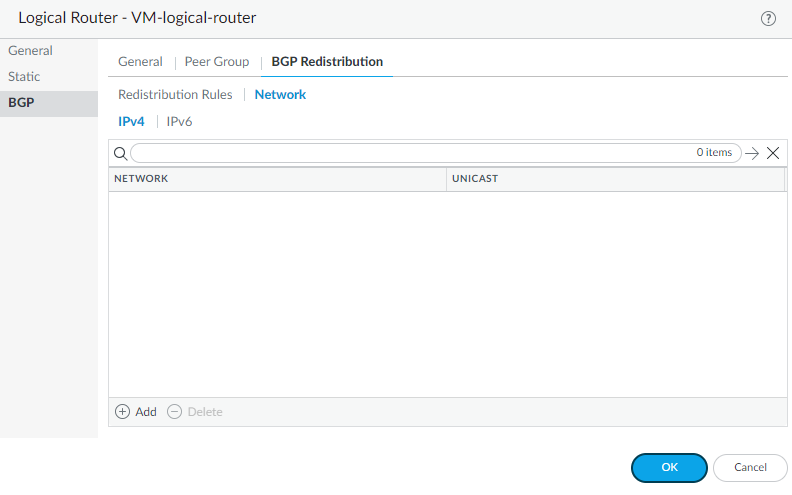
Select Network to advertise routes based on a network address.- Select IPv4 or IPv6 and Add a corresponding Network address; subnets with matching network addresses are advertised to BGP peers of the logical router.
- Select Unicast to install the matching routes into the unicast routing table of all BGP peers.
![]() Click OK to save the BGP redistribution settings.Create a BGP Authentication profile to apply to a BGP peer group or peer.
Click OK to save the BGP redistribution settings.Create a BGP Authentication profile to apply to a BGP peer group or peer.- Select .
![]() Add a BGP Authentication Profile by Name (a maximum of 31 characters).Enter the Secret and Confirm Secret. The Secret is used as a key in MD5 authentication.Click OK.Create a BGP Timers profile to apply to a BGP peer group or peer.
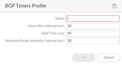
Add a BGP Authentication Profile by Name (a maximum of 31 characters).Enter the Secret and Confirm Secret. The Secret is used as a key in MD5 authentication.Click OK.Create a BGP Timers profile to apply to a BGP peer group or peer.- Select .Add a BGP Timers Profile by Name (a maximum of 31 characters).
![]() Set the Keep Alive Interval (sec)—the interval, in seconds, after which routes from the peer are suppressed according to the Hold Time setting (range is 0 to 1,200; default is 30).Set the Hold Time (sec)—the length of time, in seconds, that may elapse between successive Keepalive or Update messages from the peer before the peer connection is closed (range is 3 to 3,600; default is 90).Set the Minimum Route Advertise Interval (sec)—the minimum amount of time, in seconds, between two successive Update messages that a BGP speaker (the firewall) sends to a BGP peer that advertise routes or withdrawal of routes (range is 1 to 600; default is 30).Click OK.Create a BGP Address Family Identifier (AFI) profile to apply to a BGP peer group or peer.
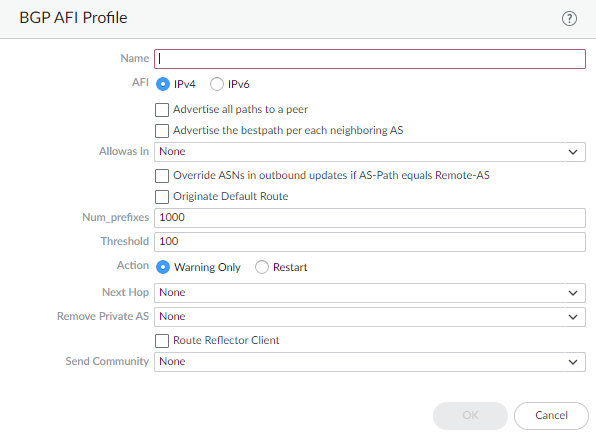
Set the Keep Alive Interval (sec)—the interval, in seconds, after which routes from the peer are suppressed according to the Hold Time setting (range is 0 to 1,200; default is 30).Set the Hold Time (sec)—the length of time, in seconds, that may elapse between successive Keepalive or Update messages from the peer before the peer connection is closed (range is 3 to 3,600; default is 90).Set the Minimum Route Advertise Interval (sec)—the minimum amount of time, in seconds, between two successive Update messages that a BGP speaker (the firewall) sends to a BGP peer that advertise routes or withdrawal of routes (range is 1 to 600; default is 30).Click OK.Create a BGP Address Family Identifier (AFI) profile to apply to a BGP peer group or peer.- Select .Add an AFI Profile by Name (a maximum of 31 characters).
![]() Select IPv4 or IPv6 AFI to specify the type of profile.Advertise all paths to a peer—Advertise all routes in the BGP routing information base (RIB) for the logical router.Advertise the best path per neighboring AS to ensure that BGP advertises the best path for each neighboring AS, and not a generic path for all autonomous systems. Disable this if you want to advertise the same path to all autonomous systems.Allow AS in:
Select IPv4 or IPv6 AFI to specify the type of profile.Advertise all paths to a peer—Advertise all routes in the BGP routing information base (RIB) for the logical router.Advertise the best path per neighboring AS to ensure that BGP advertises the best path for each neighboring AS, and not a generic path for all autonomous systems. Disable this if you want to advertise the same path to all autonomous systems.Allow AS in:- Origin—Accept routes even if the firewall’s own AS is present in the AS_PATH.
- Occurrence—Number of times the firewall’s own AS can be in the AS_PATH.
- None—(default setting) No action taken.
Override ASNs in outbound updates if AS-Path equals Remote-AS—This setting is helpful if you have multiple sites belonging to the same AS number (AS 64512, for example) and there is another AS between them. A router between the two sites receives an Update advertising a route that can access AS 64512. To avoid the second site dropping the Update because it is also in AS 64512, the intermediate router replaces AS 64512 with its own AS number (ASN), AS 64522, for example.Originate Default Route—Advertise a default route or not. Disable if you want to advertise only routes to specific destinations.Num_prefixes—Maximum number of prefixes to accept (learn) from the peer.Threshold—Percentage of the maximum number of prefixes. The prefixes are added to the BGP local RIB. If the peer advertises more than the threshold, the firewall takes the specified action (Warning Only or Restart). Range is 1 to 100.Action—Warning Only message in logs or Restart the BGP peer connection after the maximum number of prefixes is exceeded.Select the Next Hop:- Self—Causes the firewall to change the Next Hop address (in Updates it receives) to its own IP address in the Update before sending it on. This is helpful when the firewall is communicating with an EBGP router (in another AS) and with an IBGP router (in its own AS). For example, suppose the Next Hop address in a BGP Update that arrives at AS 64512 is the IP address of the egress interface of Router 2 where the Update egressed AS 64518. The Update indicates that to reach networks that Router 2 is advertising, use the Next Hop address of Router 2. However, if the firewall sends that Update to an iBGP neighbor in AS 64512, the unchanged Next Hop of Router 2 is outside AS 64512 and the iBGP neighbor does not have a route to it. When you select Self, the firewall changes the Next Hop to its own IP address so that an iBGP neighbor can use that Next Hop to reach the firewall, which in turn can reach the eBGP router.
- Self Force—
- None—(default setting) No Next Hop.
To have BGP remove private AS numbers from the AS_PATH attribute in Updates that the firewall sends to a peer in another AS, in Remove Private AS, select one of the following:- All—Remove all private AS numbers.
- Replace AS—Replace all private AS numbers with the firewall’s AS number.
- None—(default setting) No action taken.
Enable Route Reflector Client to make the BGP peers a Route Reflector client in an IBGP network.For Send Community, select the type of BGP community attribute to send in outbound Update packets:Click OK.Create a BGP Redistribution Profile to redistribute static or connected routes (that match the profile) to the BGP peers of the logical router.- Select .Add a BGP Redistribution Profile by Name (a maximum of 31 characters).
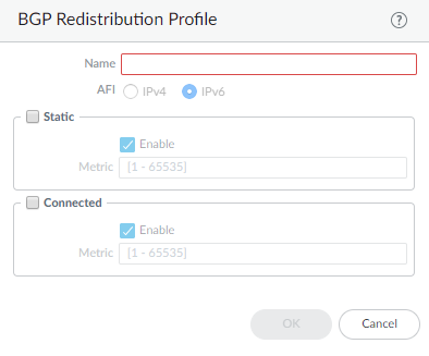
![]() Select IPv4 or IPv6 AFI to indicate the type of Redistribution profile.Select Static and Enable to redistribute IPv4 or IPv6 static routes (that match the AFI you selected) into the BGP routing information base (RIB) of the BGP peers of the logical router.Configure the Metric to apply to the static routes being redistributed into BGP (range is 1 to 65,535).Select Connected and Enable to redistribute locally connected IPv4 or IPv6 routes (that match the AFI you selected) into the BGP RIB of the BGP peers.Configure the Metric to apply to the connected routes being redistributed into BGP (range is 1 to 65,535).Click OK.(On a firewall supporting multiple virtual systems) Assign the logical router to a virtual system.
Select IPv4 or IPv6 AFI to indicate the type of Redistribution profile.Select Static and Enable to redistribute IPv4 or IPv6 static routes (that match the AFI you selected) into the BGP routing information base (RIB) of the BGP peers of the logical router.Configure the Metric to apply to the static routes being redistributed into BGP (range is 1 to 65,535).Select Connected and Enable to redistribute locally connected IPv4 or IPv6 routes (that match the AFI you selected) into the BGP RIB of the BGP peers.Configure the Metric to apply to the connected routes being redistributed into BGP (range is 1 to 65,535).Click OK.(On a firewall supporting multiple virtual systems) Assign the logical router to a virtual system.