SD-WAN
Add SD-WAN Branch or Hub Firewall
Table of Contents
Add SD-WAN Branch or Hub Firewall
Add a single SD-WAN hub or branch firewall for the Panorama
management server to manage.
| Where Can I Use This? | What Do I Need? |
|---|---|
|
Add an SD-WAN hub or branch firewall to be managed by the Panorama™ management server. When adding your devices, you specify what type of device it
is (branch or hub) and you give each device its site name for easy identification.
Before adding your devices, plan your SD-WAN configuration to ensure
that you have all the required IP addresses and you understand the SD-WAN topology. This helps in reducing any configuration errors.
If you have pre-existing zones for your Palo Alto Networks® firewalls, you
will be mapping them to the predefined zones used in SD-WAN.
If you want to have active/passive HA running on two branch firewalls or two hub
firewalls, don’t add those firewalls as SD-WAN devices at this
time. You’ll add them as HA peers separately when you configure SD-WAN devices in HA mode.
If you’re using BGP routing, you must add a Security policy rule to allow BGP
from the internal zone to the hub zone and from the hub zone to the internal
zone. If you want to use 4-byte ASNs, you must first enable 4-byte ASNs for the
virtual router.
When viewing SD-WAN devices, if no data is present or the screen
indicates that SD-WAN is undefined, check in the Compatibility Matrix that the Panorama release you’re using supports the SD-WAN plugin
release you’re trying to use.
- Select and Add a new SD-WAN firewall.
- Select the managed firewall Name to add as an SD-WAN device. You must add your SD-WAN firewalls as managed devices before you can add them as an SD-WAN device.
- Select the Type of SD-WAN device.
- Hub—A centralized firewall deployed at a primary office or location to which all branch devices connect using a VPN connection. Traffic between branches passes through the hub before continuing to the target branch, and connects branches to centralized resources at the hub location. The hub device processes traffic, enforces policy rules, and manages link swapping at the primary office or location.
- Branch—A firewall deployed at a physical branch location that connects the hub using a VPN connection and provides security at the branch level. The branch device processes traffic, enforces policy rules, and manages link swapping at the branch location.
- (Optional) (PAN-OS 10.2.8 and later 10.2 versions, and SD-WAN plugin 3.0.7 and later 3.0 versions) (PAN-OS 11.1.3 and later versions, and SD-WAN plugin 3.2.1 and later versions) Configure multiple virtual routers on the SD-WAN hub.We have introduced support for multiple virtual routers on the SD-WAN hub that enable you to have overlapping IP subnet addresses on branch devices connecting to the same SD-WAN hub. When you select the Type of SD-WAN as Hub, you will be able to configure multiple virtual routers by selecting Enable Multi-VR Support.
- For routing between the SD-WAN hub and branches:
- (SD-WAN plugin 3.0.0 and earlier versions) select Virtual Router Name in the web interface.
- (SD-WAN plugin 3.1.0 and later versions) select Router Name in the web interface.
By default, an sdwan-default virtual router is created and enables Panorama to automatically push the router configurations.(Advanced Routing enabled) (SD-WAN plugin 3.1 and later versions) If you have configured advanced routing and the logical routers are created successfully, Router Name displays both virtual and logical router names:- If the virtual router and logical router names are the same, then the Router Name displays the same name because advanced routing creates a logical router with the same name as the virtual router, by default. It's important that the logical router name and virtual router name are the same for the same template when using the advanced routing engine.
- If the virtual router and logical router names are different (which happens only when you update the logical router name manually), then the router name displays both the virtual and logical router names. You can select either virtual router (for legacy engine) or logical router (for advanced routing engine) based on your requirement. If you haven't enabled Advanced Routing, then you’ll have only virtual routers to select from the Router Name (for the legacy engine).
If you Enable Multi-VR Support:- (PAN-OS 10.2.8 and later 10.2 releases, and SD-WAN plugin 3.0.7 and later 3.0 releases) Select DIA virtual router for the Virtual Router Name.
- (PAN-OS 11.1.3 and later releases, and SD-WAN Plugin 3.2.1 and later releases) Select DIA virtual router for the Router Name.
- Enter the SD-WAN Site name to identify the geographical location or purpose of the device.The SD-WAN Site name supports all upper-case and lower-case alphanumerical and special characters. Spaces aren’t supported in the Site name and result in monitoring () data for that site not to be displayed.All SD-WAN devices, including SD-WAN devices in a high availability (HA) configuration, must have a unique Site name.
- (PAN-OS 10.0.3 and later versions) Select the Link Tag you created for the hub virtual interface (or branch virtual interface), which Auto VPN will assign to the virtual interface. You’ll use this Link Tag in a Traffic Distribution profile to allow the hub (or branch) to participate in DIA AnyPath.
- (PAN-OS 9.1.3 and later versions and SD-WAN plugin 1.0.3 and later versions) If you’re adding a hub that is behind a device performing NAT for the hub, you must specify the IP address or FQDN of the public-facing interface on that upstream NAT-performing device, so that Auto VPN configuration can use that address as the tunnel endpoint of the hub. It’s the IP address that the branch office’s IKE and IPSec flows must be able to reach. (You must have already configured Ethernet interface for SD-WAN.)
- On the Upstream NAT tab, enable Upstream NAT.
- Add an SD-WAN interface; select an interface you already configured for SD-WAN.
- Select IP Address or FQDN and enter the IPv4 address without a subnet mask (for example, 192.168.3.4) or the FQDN of the upstream device, respectively.
- Click OK.Additionally, on the upstream device that is performing NAT you must set up the inbound destination NAT with a one-to-one NAT policy, and you must not configure port translation to the IKE or IPSec traffic flows.If the IP address on the upstream device changes, you must configure the new IP address and push it to the VPN cluster. You must use the CLI commands clear vpn ipsec-sa, clear vpn ike-sa, and clear session all on both the branch and hub. You must also clear session all on the virtual router where you configured the NAT policy for the IP addresses.Upstream NAT isn’t supported on Layer 2 interfaces.
- (Required for pre-existing customers) Map your pre-existing zones to predefined zones used for SD-WAN.When you map your existing zones to an SD-WAN zone, you must modify your security policy rules and add the SD-WAN zones to the correct Source and Destination zones.
- Select Zone Internet and Add the pre-existing zones that will egress SD-WAN traffic to the internet.
- Select Zone to Hub and Add the pre-existing zones that will egress SD-WAN traffic to the hub.
- Select Zone to Branch and Add the pre-existing zones that will egress SD-WAN traffic to the branch.
- Select Zone Internal and Add the pre-existing zones that will egress SD-WAN traffic to an internal zone.
- (PAN-OS 10.0.3 and later versions) (Full Mesh Deployments Only) If you’re adding a branch that is behind a device performing NAT for the branch, you must specify the IP address or FQDN of the public-facing interface on that upstream NAT-performing device, or select DDNS to indicate that the IP address for the interface on the NAT device is obtained from the Palo Alto Networks DDNS service. Thus, Auto VPN Configuration uses that public IP address as the tunnel endpoint for the branch. It is the IP address that the branch office’s IKE and IPSec flows must be able to reach. (You must have already configured Ethernet interface for SD-WAN.)
- On the Upstream NAT tab, enable Upstream NAT.
- Add an SD-WAN interface; select an interface you already configured for SD-WAN.
- If you select the NAT IP Address Type to be Static IP, select IP Address or FQDN and enter the IPv4 address without a subnet mask (for example, 192.168.3.4) or the FQDN of the upstream device, respectively.
- Alternatively, select the NAT IP Address Type to be DDNS.
- Click OK.Additionally, on the upstream device that is performing NAT you must set up the inbound destination NAT with a one-to-one NAT policy, and you must not configure port translation to the IKE or IPSec traffic flows.If the IP address on the upstream device changes, you must configure the new IP address and push it to the VPN cluster. You must use the CLI commands clear ipsec, clear ike-sa, and clear session all on both the branch and hub. You must also clear session all on the virtual router where you configured the NAT policy for the IP addresses.There is a second location in the web interface where you can configure Upstream NAT for a branch, but the following location isn't preferred and you shouldn't configure Upstream NAT for a branch in both places. The secondary, non-preferred location to configure Upstream NAT is on Panorama at , select a template in the Template field, select an Ethernet interface, and select the SD-WAN tab. At this point you can Enable Upstream NAT, and select a NAT IP Address Type. This second method takes precedence. If Upstream NAT is first configured for the Ethernet interface on Panorama through the template stack, then the SD-WAN plugin won’t change the settings, even if you use different settings on the plugin device configuration page. Only if there is no Upstream NAT configured on Panorama through the template stack, then the plugin configuration for Upstream NAT takes effect.Upstream NAT is not supported on Layer 2 interfaces.
- (PAN-OS 10.1.5-h1 and later 10.1 versions, and SD-WAN plugin 2.2.1 and later 2.2 versions) (PAN-OS 10.2.1 and later versions, and SD-WAN plugin 3.0.1 and later versions) If your application traffic is tagged with Type of Service (ToS) bits or Differentiated Services Code Point (DSCP) markings, copy the ToS field from the inner header to the outer VPN header of encapsulated packets going through the VPN tunnel to preserve QoS information.
- Select the VPN Tunnel tab.
- Select Copy ToS Header.
- Click OK.
- (Mandatory) (SD-WAN plugin 3.2.0 and later versions) Specify how to authenticate the peer.Select the Authentication type: Pre Shared Key or Certificate. If you choose a pre-shared key, the pre-shared key will be automatically generated.

- You must use a unique certificate for each device in the SD-WAN cluster.
- You can't change the authentication type after adding an SD-WAN device to the VPN cluster.
- (HA deployments only) If you have set up a high availability (HA) pair in Panorama, then both the active and passive firewalls must use the same certificate. During the RMA process, you must configure the replacement firewall with the same certificate as the active firewall. If the certificate of an active firewall is revoked and a new certificate is pushed, then the passive firewall must also be updated with the new certificate. That is, both active and passive firewalls must have the same certificate configured in a high availability deployment.
- (Only if enabling Certificate authentication type) (SD-WAN plugin 3.2.0 and later versions) Configure certificate-based authentication.
- Select a Local Certificate—one that is already on the Panorama, Import a certificate, or Generate a new certificate.
- If you need to Import a certificate, then first Import a Certificate for IKEv2 Gateway Authentication and then return to this task. We do not support SCEP-generated certificates.
- If you want to Generate a new
certificate, then first generate a certificate on the
Panorama and then return to this task. The generated
certificate must be unique for each SD-WAN
device. That is, you can't generate a certificate and share it
among multiple SD-WAN devices.Keep the following in mind while generating the branch and hub firewall certificates that are used for SD-WAN tunnel authentication:
- Two different hub devices can use the same hub certificate.
- Two different branch devices can use the same branch
certificate if the following conditions are met:
- Branch devices are not part of the same VPN cluster.
- There is no common hub device between the VPN clusters that these branch device would be part of.
- (HA deployments only) Two different branch devices can also have the same branch certificates if they are configured as HA members.
- If you've a common hub device between the VPN
clusters, then the branch devices that are part of
these VPN clusters should have unique certificates
containing with unique values for all its
attributes. If you don't ensure the uniqueness of
the certificate and its values, then commit will
fail on the hub device (no commit failure on Panorama). Also ensure that the leaf certificates (branch and hub firewall certificates) used for SD-WAN tunnel authentication are generated meeting the following criteria:
- Key usage should have digital signatures.
- All certificates must be signed by the same root CA.
- The device certificate must be directly signed by the root CA.
- Certificate format should be PKCS12.
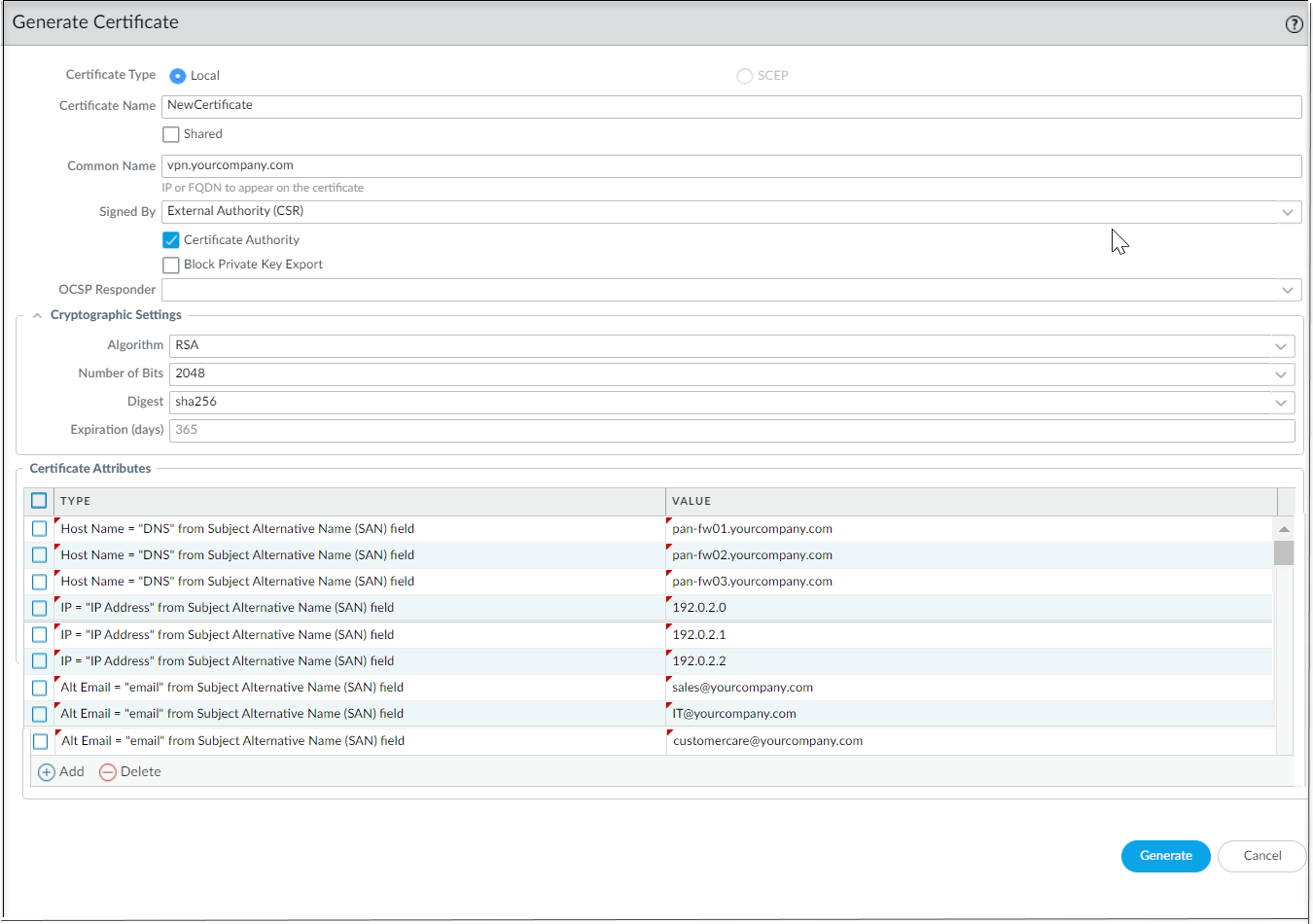
- The certificate attributes are used for determining the local ID
and peer ID for IKE gateways. Hence, the leaf certificates, that
is, the branch and hub firewall certificates that are used for
SD-WAN tunnel authentication, must be
generated with the following three certificate attributes and
each certificate attribute should be assigned with three unique
attribute values. Otherwise, a commit error will be thrown.
- FQDN (Host Name)
- IP address (IP)
- User FQDN (Alt Email)
It is mandatory to have unique Host Name, IP, and Alt Email certificate attributes among all certificates. That is, none of the certificates should have these attribute values in common.In the below example, NewCertificate is generated with the total of nine mandatory certificate attributes. The Host Name certificate attribute is configured with three unique attribute values: pan-fw01.yourcompany.com, pan-fw02.yourcompany.com, and pan-fw03.yourcompany.com. The IP certificate attribute is configured with three unique attribute values: 192.0.2.0, 192.0.2.1, and 192.0.2.2. The Alt Email certificate attribute is configured with three unique attribute values: sales@yourcompany.com, IT@yourcompany.com, and customercare@yourcompany.com.
- (Optional) Choose a Certificate Profile. A certificate profile contains information about how to authenticate the peer gateway.
- (Optional) Enable strict validation of peer’s extended key use to control strictly how the key can be used.
- (Optional) (SD-WAN plugin 3.1.0 and earlier versions) Configure Border Gateway Protocol (BGP) routing.To automatically set up BGP routing between the VPN cluster members, enter the BGP information below. If you want to manually configure BGP routing on each firewall or use a separate Panorama template to configure BGP routing for more control, leave the BGP information below blank.Before implementing SD-WAN with BGP routing in an environment where BGP is already in use, ensure that the BGP configuration generated by the SD-WAN plugin doesn’t conflict with your pre-existing BGP configuration. For example, you must use the existing BGP AS number and router ID values for the corresponding SD-WAN device values. If the BGP configuration generated by the plugin conflicts with your pre-existing BGP configuration, the pre-existing BGP configuration takes precedence. If you want the pushed configuration to take precedence, you must enable the force template value when doing a Panorama push.
- Select the BGP tab and enable BGP to configure BGP routing for SD-WAN traffic.
- Enter the BGP Router ID, which must be unique among all routers.
- Specify a static IPv4 Loopback Address for BGP peering. Auto VPN configuration automatically creates a Loopback interface with the same IPv4 address that you specify. If you specify an existing loopback address, the commit will fail, so you should specify an IPv4 address that is not already a loopback address.
- Enter the AS Number. The autonomous system number specifies a commonly defined routing policy to the internet. The AS number must be unique for every hub and branch location.
- (SD-WAN plugin 2.0.2 and later versions) Disable the Remove Private AS option (the default is enabled) if you have endpoints that need to exchange routes with a hub or branch firewall in an SD-WAN BGP topology and therefore you don’t want to remove private AS numbers (64512 to 65534) from the AS_PATH attribute in BGP Updates. In this case, you want to allow the private AS numbers to leave the SD-WAN private AS in BGP Updates.The Remove Private AS setting applies to all BGP peer groups on the branch or hub firewall. If you need this setting to differ among BGP peer groups or peers, you must configure the setting outside of the SD-WAN plugin.If you change the Remove Private AS setting, commit to all SD-WAN cluster nodes, and subsequently downgrade to an SD-WAN plugin version earlier than 2.0.2, then all configuration related to Remove Private AS must be done outside of the SD-WAN plugin or directly on the firewalls.
- Enter Prefix(es) to Redistribute. On a hub device, you must enter at least one prefix to redistribute. Branch devices do not have this option; subnets connected to branch locations are redistributed by default.
- (SD-WAN plugin 3.1.1 and later versions using the legacy routing engine) To configure BGP to use IPv4, select IPv4 BGP. Whether your BGP environment is only IPv4 or dual stack (IPv4 and IPv6), you must enable IPv4 BGP.
- Enable IPv4 BGP support.For an upgraded configuration (an already existing SD-WAN IPv4 configuration), Enable IPv4 BGP support is selected by default. Otherwise, explicitly Enable IPv4 BGP support.
- Specify a static IPv4 Loopback Address for BGP peering. Auto VPN configuration automatically creates a Loopback interface with the same IPv4 address that you specify. If you specify an existing loopback address, the commit will fail, so you must specify an IPv4 address that isn’t already a loopback address.
- Disable the Remove Private AS option (the default is enabled) if you have endpoints that need to exchange routes with a hub or branch firewall in an SD-WAN BGP topology and therefore you don’t want to remove private AS numbers (64512 to 65534) from the AS_PATH attribute in BGP Updates. In this case, you want to allow the private AS numbers to leave the SD-WAN private AS in BGP Updates.The Remove Private AS setting applies to all BGP peer groups on the branch or hub firewall. If you need this setting to differ among BGP peer groups or peers, you must configure the setting outside of the SD-WAN plugin.If you change the Remove Private AS setting, commit to all SD-WAN cluster nodes, and later downgrade to an SD-WAN plugin version earlier than 2.0.2, then you must perform all configuration related to Remove Private AS outside of the SD-WAN plugin or directly on the firewalls.
- Add the Prefix(es) to Redistribute. On a hub device, you must enter at least one prefix to redistribute over the SD-WAN tunnel. Branch devices don't have this mandatory configuration requirement because subnets connected to branch locations are redistributed by default.
- (SD-WAN plugin 3.1.1 and later versions using the legacy routing engine) To configure BGP to use IPv6, select IPv6 BGP.
- Enable IPv6 BGP support.
- Specify a static IPv6 Loopback Address for BGP peering. Auto VPN configuration automatically creates a loopback interface with the same IPv6 address that you specify. If you specify an existing loopback address, the commit will fail, so you must specify an IPv6 address that isn't already a loopback address.
- Add the Prefix(es) to Redistribute over the SD-WAN tunnel. On a hub device, you must enter at least one prefix to redistribute over the SD-WAN tunnel. Branch devices don't have this mandatory configuration requirement because subnets connected to branch locations are redistributed by default.
- Click OK.
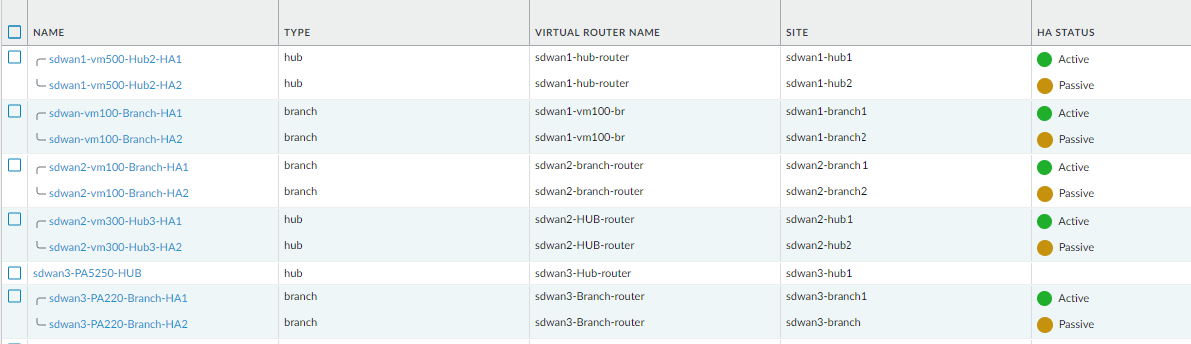
- (SD-WAN plugin 1.0.1 and later versions) Select Group HA Peers at the bottom of the screen to display branches (or hubs) that are HA peers together.
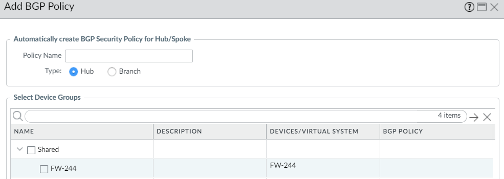
- (PAN-OS 9.1.2 and later versions, and SD-WAN plugin 1.0.2 and later versions) Have Panorama create and push to firewalls a Security policy rule that allows BGP to run between branches and hubs.
- (SD-WAN plugin 3.1.0 and earlier versions) Select BGP Policy at the bottom of the screen and Add.
- (SD-WAN plugin 3.1.1 and later versions) At the bottom of the screen, select IPv4 BGP Policy or IPv6 BGP Policy and Add a policy rule.
- Enter a Policy Name for the Security policy rule that Panorama will automatically create.
- (SD-WAN plugin 3.2.0 and later versions) Select Type as Hub or Branch.
- Select Device Groups to specify the device groups to which Panorama pushes the Security policy rule.
- Click OK.
- Select Push to Devices to push your configuration changes to your managed firewalls.