Connect Power to a PA-400 Series Firewall
Table of Contents
Expand all | Collapse all
Connect Power to a PA-400 Series Firewall
Power the PA-400 Series firewall with DC power after converting the current from a
connected AC power source.
The following procedure describes how to connect power to a PA-415,
PA-415-5G, PA-440, PA-445, PA-450, PA-455, PA-455-5G, and PA-460 firewall.
- The PA-415, PA-415-5G, PA-440, PA-445, PA-450, PA-455, and PA-460 firewalls use DC power.
- The PA-455-5G firewall uses AC power.
To avoid injury to yourself or damage to your Palo Alto Networks® hardware or the
data that resides on the hardware, read the Safety Warnings.
Learn
how to Set Up a Connection to the Firewall based on your desired
boot mode prior to powering on the firewall for the first time.
(PA-415 and PA-445 only) A
ground connection is not required during normal operation. For these firewalls, skip
to Step 3 of the following procedure.
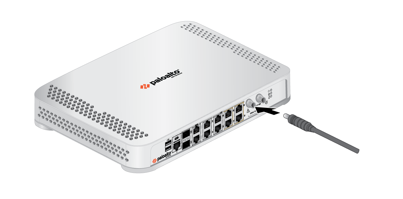
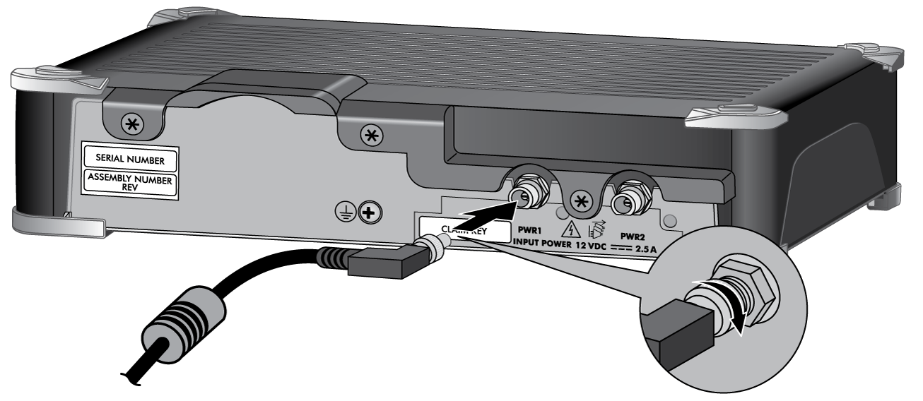
- Remove the screw and star washer from the ground point on the back of the firewall.Crimp a 14AWG ground cable to a ring lug (cable and lug not included), place the ring lug over the screw and star washer, then replace the screw to attach the cable to the firewall. Torque the screw to 25 in-lbs and then connect the other end of the cable to earth ground.Connect the connector from the power adapter into the PWR 1 port on the firewall and tighten the connector nut to secure the cable to the firewall.The power adapter inputs for the PA-440, PA-450, and PA-460 are on the back panel of the device. The power adapter inputs for the PA-415, PA-415-5G, PA-455, PA-455-5G, and PA-445 are on the front panel of the device.Ensure the power adapter itself is appropriately positioned (see Install the PA-400 Series Firewall).(PA-415, PA-415-5G, PA-455, PA-455-5G, and PA-445 (PA-415 pictured))
![]() (PA-440, PA-450, and PA-460)
(PA-440, PA-450, and PA-460)![]() Plug the connector from the power adapter into your power source. After power is connected, the firewall powers on as indicated by the green power LED next to the PWR 1 port. The front PWR LED shows green when a functioning power adapter is connected.(Optional for PA-415, PA-415-5G, PA-440, PA-445, PA-455-5G, PA-450, and PA-460) Plug the connector from a second power adapter (purchased separately) into the PWR 2 port and plug the connector into a power source.For the PA-415, PA-415-5G, PA-440, PA-445, PA-450, PA-455, PA-455-5G, and PA-460, connect the second power adapter through a different circuit breaker to provide power redundancy and to allow for electrical circuit maintenance.On the PA-440, PA-450, and PA-460, the control check on the power supply can detect if a connection is present but does not check for voltage. As a result, if the power cable is connected to the firewall but disconnected from a power source, the system still reads the power connection as inserted.On some PA-440, PA-450, and PA-460 models, the show system environmentals command in the CLI displays the status of a second power supply when a second power supply is not connected.Before powering on the firewall, ensure that you have connected your Ethernet cables in accordance to the mode you wish to boot the firewall in (standard mode or Zero Touch Provisioning mode) as specified in Set Up a Connection to the Firewall.
Plug the connector from the power adapter into your power source. After power is connected, the firewall powers on as indicated by the green power LED next to the PWR 1 port. The front PWR LED shows green when a functioning power adapter is connected.(Optional for PA-415, PA-415-5G, PA-440, PA-445, PA-455-5G, PA-450, and PA-460) Plug the connector from a second power adapter (purchased separately) into the PWR 2 port and plug the connector into a power source.For the PA-415, PA-415-5G, PA-440, PA-445, PA-450, PA-455, PA-455-5G, and PA-460, connect the second power adapter through a different circuit breaker to provide power redundancy and to allow for electrical circuit maintenance.On the PA-440, PA-450, and PA-460, the control check on the power supply can detect if a connection is present but does not check for voltage. As a result, if the power cable is connected to the firewall but disconnected from a power source, the system still reads the power connection as inserted.On some PA-440, PA-450, and PA-460 models, the show system environmentals command in the CLI displays the status of a second power supply when a second power supply is not connected.Before powering on the firewall, ensure that you have connected your Ethernet cables in accordance to the mode you wish to boot the firewall in (standard mode or Zero Touch Provisioning mode) as specified in Set Up a Connection to the Firewall.


