Install the PA-400 Series Firewall Using the PAN-PA-400-RACKTRAY
Table of Contents
Install the PA-400 Series Firewall Using the PAN-PA-400-RACKTRAY
Install a PA-400 Series firewall in an equipment rack
using mounting brackets and rails.
Up to two individual PA-440, PA-450, or PA-460
firewalls can be mounted in a 19” equipment rack using the PAN-PA-400-RACKTRAY.
The mounting equipment requires 1 RU of rack space.
One PA-415-5G firewall can be mounted in a 19” equipment
rack using the PAN-PA-5G-RACKTRAY-ANT-CABLE. The mounting equipment requires 1 RU of
rack space.
One PA-455 or PA-455-5G
firewall can be mounted in a 19” equipment rack using the PAN-1RU-SMALL-RACK4. The
mounting equipment requires 1 RU of rack space.
One PA-415
or PA-445 firewall can be mounted in a 19” equipment rack using the
PAN-PA-400-POE-RACKTRAY. This mounting equipment requires 1RU of
rack space.
If you have a firewall
that supports multi-band antennas, make sure that you read how to install antennas on the 5G firewall before
continuing with this procedure.
The procedure to install each set of mounting equipment is the same unless specified
otherwise.
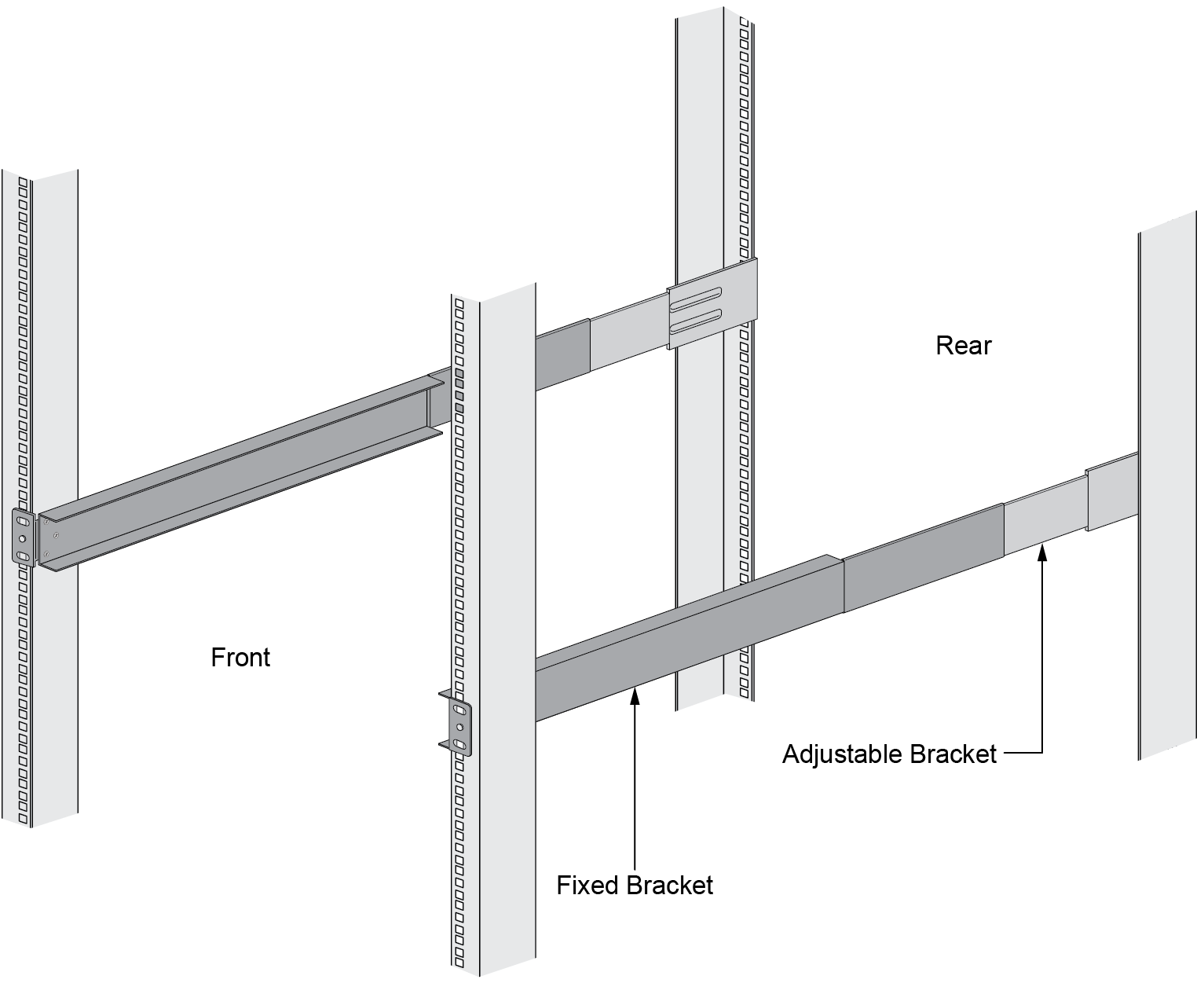
- Slide one of the adjustable mounting brackets into one of the fixed mounting brackets to create a mounting rail. Repeat for the second mounting rail. The adjustable and fixed brackets are the same for the left and right side.
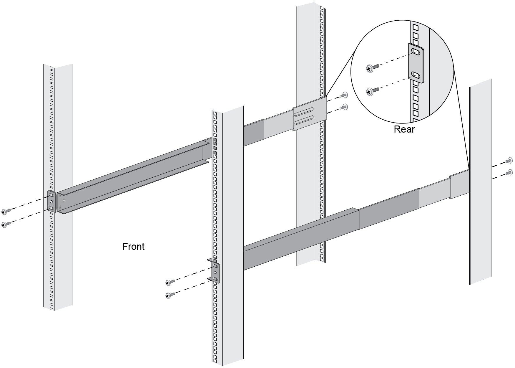
![]() Align the bottom edge of the mounting rails to the bottom of the 1 RU reserved for your firewall. Align the slotted holes in the adjustable mounting bracket to the holes on the rear of the equipment frame.The mounting rails are designed for equipment frames that are 26” to 32” deep.Secure the rails to the equipment frame with mounting screws (not provided) compatible with your equipment frame. Tighten the screws to their recommended torque value.
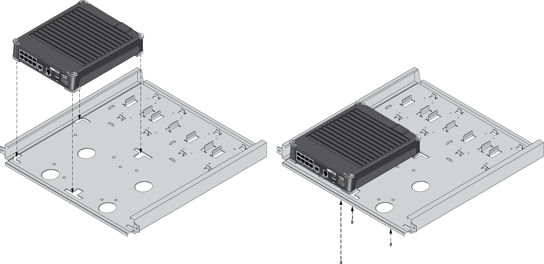
Align the bottom edge of the mounting rails to the bottom of the 1 RU reserved for your firewall. Align the slotted holes in the adjustable mounting bracket to the holes on the rear of the equipment frame.The mounting rails are designed for equipment frames that are 26” to 32” deep.Secure the rails to the equipment frame with mounting screws (not provided) compatible with your equipment frame. Tighten the screws to their recommended torque value.![]() With the front of the firewall facing forward, align the four rubber feet on the bottom of the device to the slotted holes in the provided mounting tray.(PA-440, PA-450, and PA-460 firewalls)
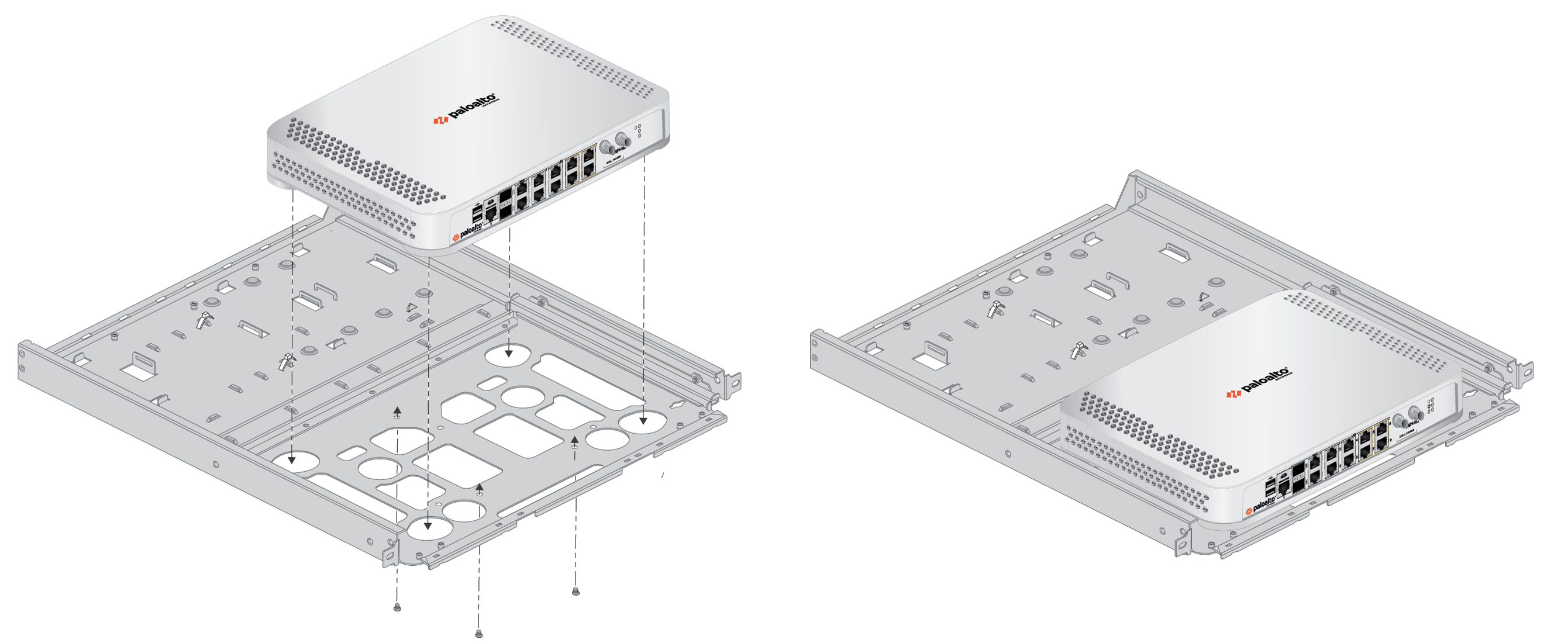
With the front of the firewall facing forward, align the four rubber feet on the bottom of the device to the slotted holes in the provided mounting tray.(PA-440, PA-450, and PA-460 firewalls)![]() (PA-415, PA-415-5G, PA-455, PA-455-5G, and PA-445 firewalls)
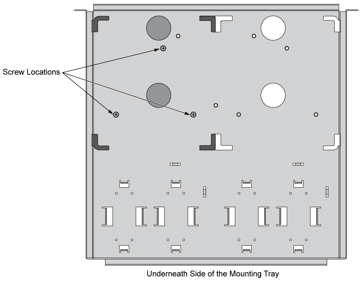
(PA-415, PA-415-5G, PA-455, PA-455-5G, and PA-445 firewalls)![]() While holding the firewall, carefully flip the mounting tray over to reveal its underside.Secure the firewall in place using three of the provided #6-32 x 3/16” Long Flathead screws.(PA-440, PA-450, and PA-460 firewalls)
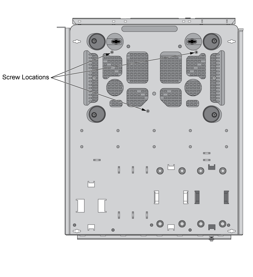
While holding the firewall, carefully flip the mounting tray over to reveal its underside.Secure the firewall in place using three of the provided #6-32 x 3/16” Long Flathead screws.(PA-440, PA-450, and PA-460 firewalls)![]() (PA-415, PA-415-5G, PA-455, PA-455-5G, and PA-445 firewalls)
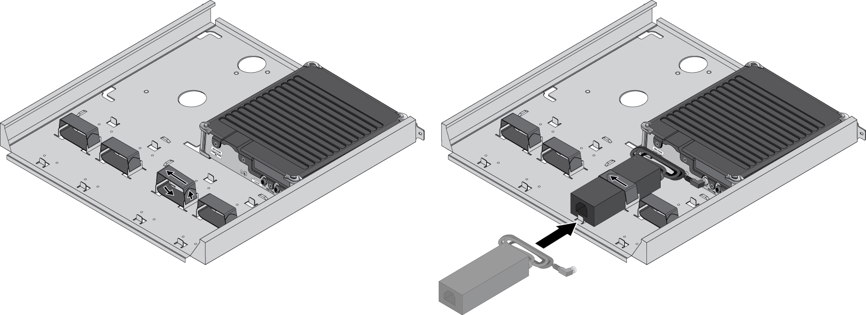
(PA-415, PA-415-5G, PA-455, PA-455-5G, and PA-445 firewalls)![]() (If mounting a second firewall) Repeat Steps 4 through 6 for the second firewall. Place the second firewall adjacent to the first firewall in the mounting tray.Flip the mounting tray back into an upright position.Slide the firewall power supply into the marked position. Fasten the provided velcro strap around the power supply until it is secure in place.(PA-440, PA-450, and PA-460 firewalls)
(If mounting a second firewall) Repeat Steps 4 through 6 for the second firewall. Place the second firewall adjacent to the first firewall in the mounting tray.Flip the mounting tray back into an upright position.Slide the firewall power supply into the marked position. Fasten the provided velcro strap around the power supply until it is secure in place.(PA-440, PA-450, and PA-460 firewalls)![]() (PA-415, PA-415-5G, PA-455, PA-455-5G, and PA-445 firewalls)
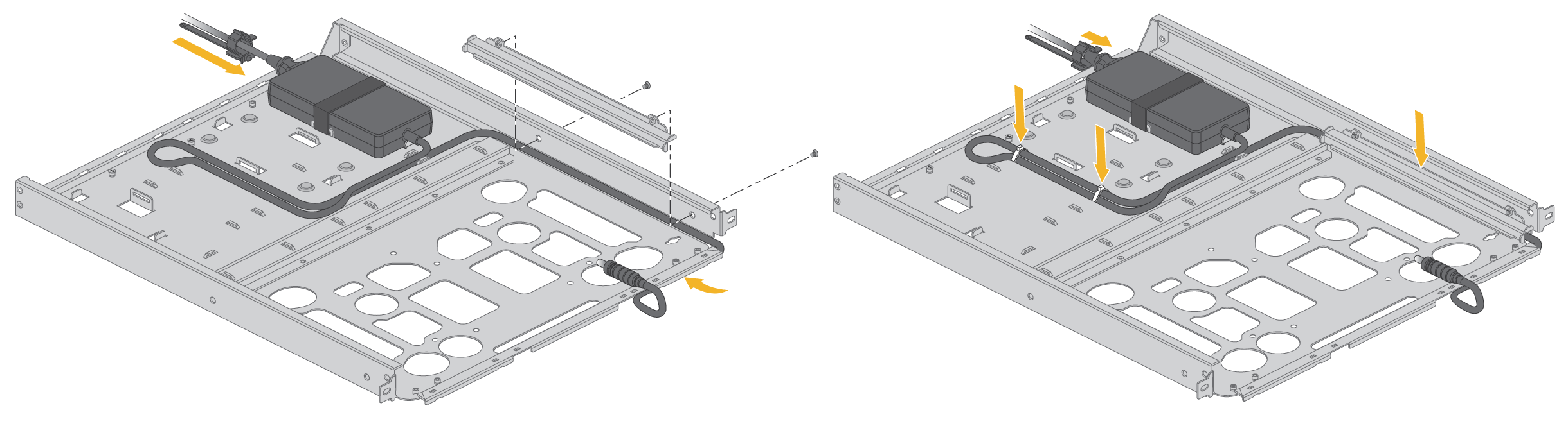
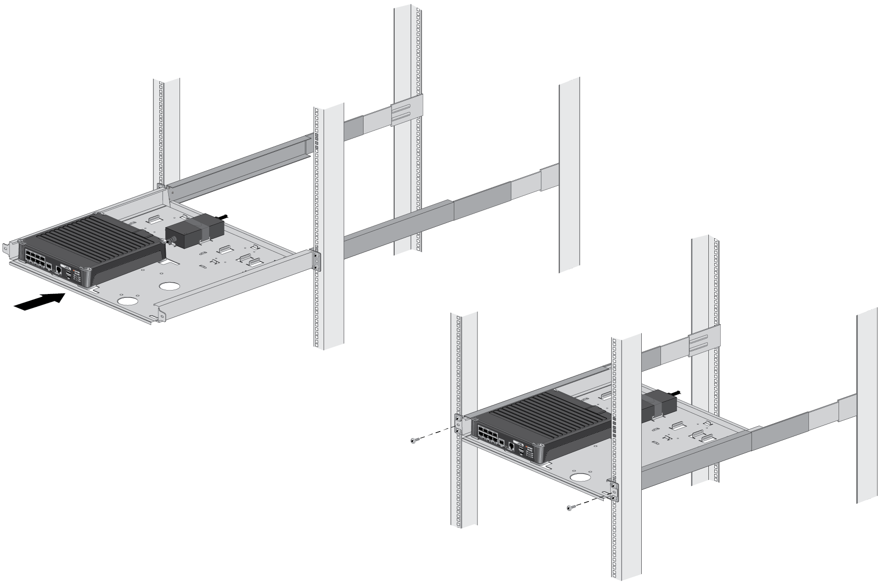
(PA-415, PA-415-5G, PA-455, PA-455-5G, and PA-445 firewalls)![]() For the PA-415 and PA-445 firewalls, use the provided bracket to keep the power adapter cable in place.Plug the power supply connector into the back or front of the firewall depending on where the power input is located. Using the provided tie-wraps, bind and secure the power supply cable to the metal hooks in the mounting tray.A redundant power supply can be mounted in the available position next to the primary power supply.(If mounting a second firewall) Repeat Steps 9 and 10 for the power supplies of the second firewall.Slide the mounting tray into the rails previously fixed to the equipment rack. Stop when the front flange on the mounting tray is flush with the front of the rail.Align the slotted holes in the mounting tray to the holes in the equipment frame. Secure the mounting tray to the equipment frame on both sides using 3 screws each (not provided). The screws must be compatible with your equipment frame.(PA-440, PA-450, and PA-460 firewalls)
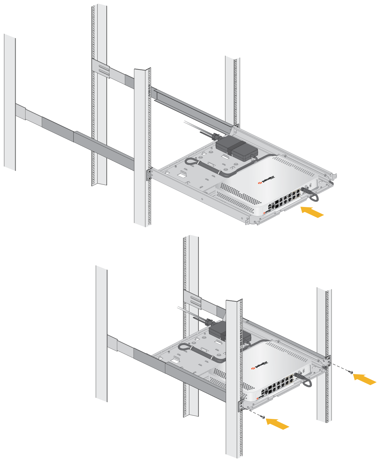
For the PA-415 and PA-445 firewalls, use the provided bracket to keep the power adapter cable in place.Plug the power supply connector into the back or front of the firewall depending on where the power input is located. Using the provided tie-wraps, bind and secure the power supply cable to the metal hooks in the mounting tray.A redundant power supply can be mounted in the available position next to the primary power supply.(If mounting a second firewall) Repeat Steps 9 and 10 for the power supplies of the second firewall.Slide the mounting tray into the rails previously fixed to the equipment rack. Stop when the front flange on the mounting tray is flush with the front of the rail.Align the slotted holes in the mounting tray to the holes in the equipment frame. Secure the mounting tray to the equipment frame on both sides using 3 screws each (not provided). The screws must be compatible with your equipment frame.(PA-440, PA-450, and PA-460 firewalls)![]() (PA-415, PA-415-5G, PA-455, PA-455-5G, and PA-445 firewalls)
(PA-415, PA-415-5G, PA-455, PA-455-5G, and PA-445 firewalls)![]() Proceed to Connect Power to a PA-400 Series Firewall
Proceed to Connect Power to a PA-400 Series Firewall