Configure 5G Network Slice Security
Table of Contents
Configure 5G Network Slice Security
Configure 5G network slice security.
After you’ve read about 5G Network Slice Security, prepare
to configure network slice security. Gather the IP addresses of
the following devices in your topology so that you can use these
addresses in Security policy rules controlling traffic to and from
these devices:
- gNodeB (gNB)
- Access and Mobility Management Function (AMF)
- Session Management Function (SMF)
- User Plane Function (UPF)
- Enable GTP security.
- Select . Select GTP Security.
- Click OK.
- Commit the change.
- Select and Reboot Device.
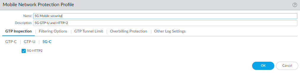
- Enable inspection of 5G HTTP/2 control packets; create
a Mobile Network Protection profile.
- Select .
- Add a profile by Name, for example, 5G Mobile security.
- Enter a Description.
- On the GTP Inspection tab, select 5G-C.
- Enable 5G-HTTP2 to enable inspection
of 5G HTTP/2 control packets.
![]()
- Select GTP-U and enable GTP-U Content Inspection to correlate context from 5G HTTP/2 control packets (Subscriber IDs and Equipment IDs) to IP user traffic inside a GTP-U tunnel.
- Select Filtering Options and RAT Filtering;
for example, you can allow NR (New Radio)
and block other RATs.
![]()
- Select IMSI Filtering and Add one or more IMSI Prefix(es) with the desired action.
- Select APN Filtering and Add one or more APNs with the desired action.
- (Optional) To troubleshoot, select Other Log Settings and select 5G Allowed Messages N11 (the HTTP/2 control messages). You can also enable GTP-U Allowed Messages for Tunnel Management, Path Management, and G-PDU. You can Log User Location.
- Click OK.
- Create address objects for the IP addresses assigned to the network elements in your topology, such as the AMF on the N11 interface, the gNB on the N3 interface, the SMF on the N11 interface, and the UPF on the N3 interface.
- Create a Security policy rule that applies your Mobile
Network Protection profile to application traffic.
- Select and Add a Security policy rule by Name.
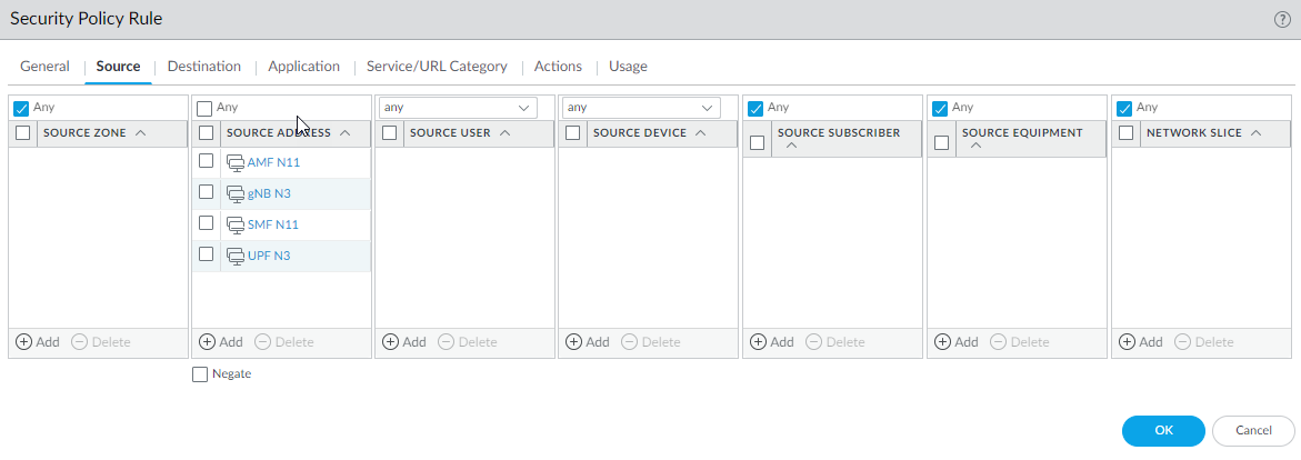
- Select Source tab and Add a Source Zone or select Any.
- For Source Address, Add the
address objects for the 5G element endpoints on the N3 and N11 interfaces
that you want to allow.
![]()
- For Destination, Add the Destination Address address objects for the 5G element endpoints on the N3 and N11 interfaces that you want to allow (the same ones you allowed for Source Address).
- Add the Applications to allow, such as the user plane, which is gtp-u and web-browsing, which has HTTP/2.
- On the Actions tab, select the Action, such as Allow.
- Select the Mobile Network Protection profile you created.
- Select other profiles you want to apply, such as Vulnerability Protection.
- Select Log Settings, such as Log at Session Start and Log at Session End.
- Click OK.
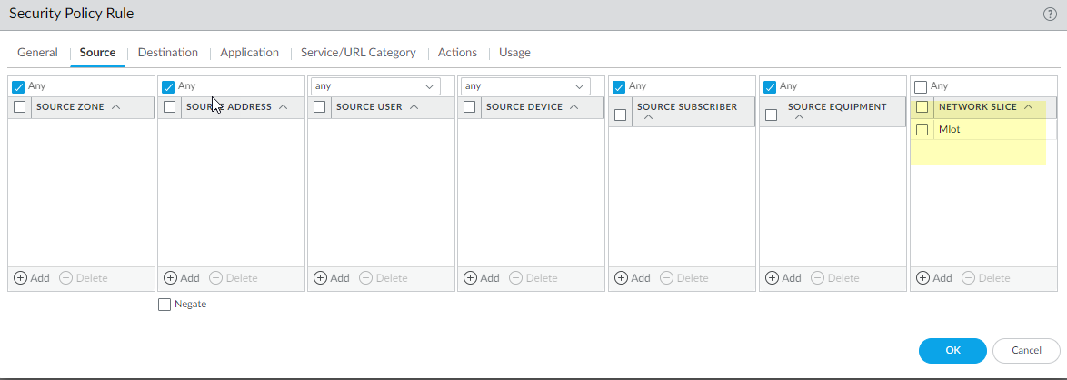
- Create another Security policy rule based on Network
Slices, for example, to allow applications for a standardized or
operator-specific SST.
- Select and Add a Security policy rule by Name.
- Select Source and Add one
or more Network Slices in either of the following
formats:
- Standardized SST (select eMBB, MIoT, or URLLC).
- Operator-specific SSTs in the format of text,number (number range is 128 to 255, in decimal). (The number appears in hexadecimal in logs.)
![]()
- (Optional) You can add Source Subscriber and Source Equipment names to this Security policy rule to make the rule more restrictive.
- Specify Source Zone, Source Address, Source User, and Source Device, or use the default Any setting for each.
- Specify Destination Zone, Destination Address, and Destination Device, or use the default Any setting for each.
- For Applications, select, for example, modbus and web-browsing.
- On the Actions tab, select the Action, such as Allow.
- Select profiles you want to apply, such as Antivirus, Vulnerability Protection, Anti-Spyware, URL Filtering, File Blocking, and WildFire Analysis.
- Select Log Settings, such as Log at Session Start and Log at Session End.
- Click OK.
- Commit.