Configure Intelligent Security Using GTP for User Equipment to IP Address Correlation
Table of Contents
Configure Intelligent Security Using GTP for User Equipment to IP Address Correlation
Learn how to configure Intelligent Security using GTP for user equipment to IP
address Correlation for Security policy enforcement.
User equipment to IP address correlation using GTP requires
PAN-OS 11.2 and later versions.
If you select GTP as the source of the traffic that you want to inspect using
Intelligent Security to map the IMSI or IMEI to subscriber or user IP addresses, you
can also:
- apply GTP protocol (including GTPv1-C, GTPv2-C, and GTP-U) security with validity checks
- perform a mandatory IE check
- check GTP-in-GTP traffic
- use RAT, IMSI, or Access Point Name (APN) filtering
- get visibility for important mobility context information contained in GTP session start or session end logs
Intelligent Security using GTP does not support:
- GTP stateful inspection and GTP message order check
- Validation for GTP-U tunnel setup
- End User IP address Spoofing
- User Equipment to IP address (UEIP) Assignment using DHCP for 4G or 3G networks
Intelligent Security using GTP supports the following deployments:
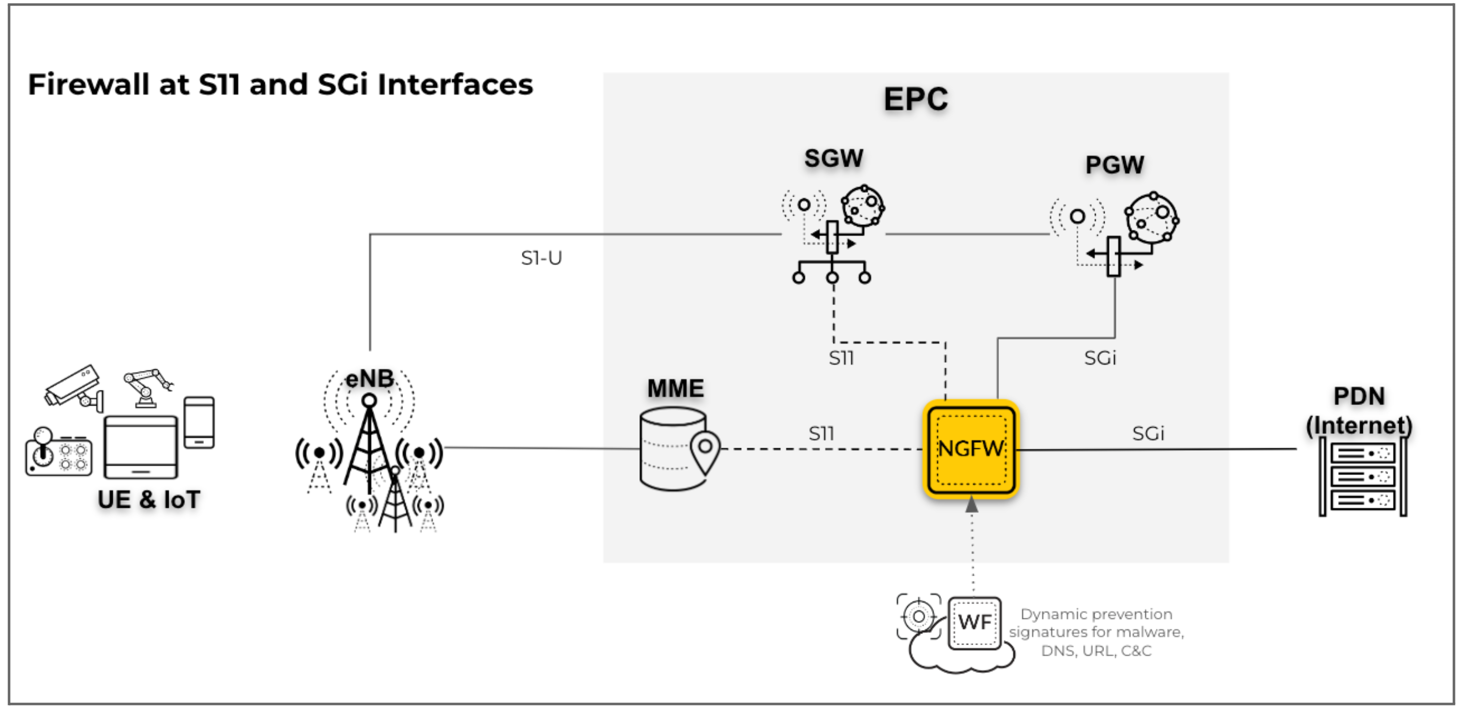
- Perimeter security on the SGi interface with GTP traffic on the S11
interfaces in a 4G network: For this scenario, deploy the firewall for
perimeter security on the SGi interface and map user equipment (UE) to IP
addresses for UE subscriber and equipment traffic. The firewall inspects the
GTPv2-C protocol traffic on the S11 interface.
![]()
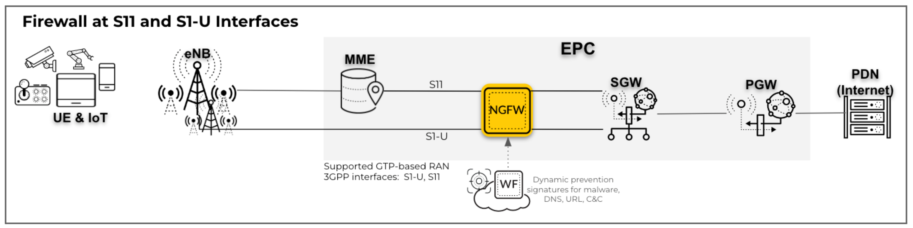
- RAN security on the S1-U interface with GTP traffic on the S11 interfaces in
a 4G network: In this configuration, deploy the firewall for RAN
security on the S1-U or GTP-U interface and map the UE to IP addresses for UE
subscriber and equipment traffic. The firewall inspects the GTPv2-C protocol
traffic on the S11 interface.
![]()
- Core security on the S5-U interface with GTP traffic on the S5-C interfaces
in a 4G network: For this scenario, deploy the firewall on the S5-U
interface and map the UE to IP addresses for UE subscriber and equipment
traffic. The firewall inspects the GTPv2-C protocol traffic on the S5 or S8-C
interface.
![]()
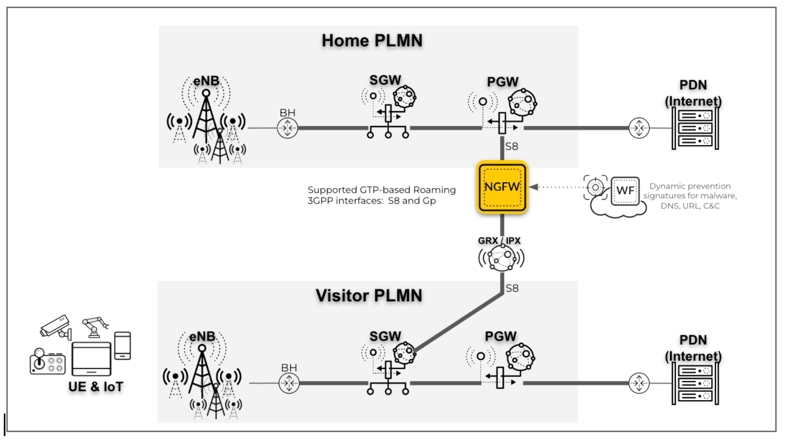
- Roaming security on the S8-U interface with the GTP traffic on S8-C
interfaces in a 4G network: In this scenario, deploy the firewall on the
S8-U interface and map UE to IP addresses for UE subscriber and equipment
traffic. The firewall inspects the GTPv2-C protocol traffic on the S8-C
interface.
![]()

- Enable GTP Security.
- Log in to the firewall web interface.Select then select GTP Security.Click OK.Commit the change.Select and Reboot Device.Create a Mobile Network Protection Profile.
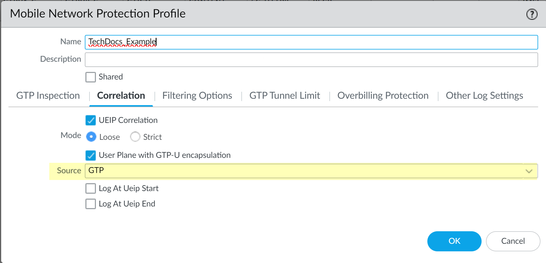
- Select and Add a new profile.Give the profile a unique Name.Select Correlation and enable UEIP Correlation.Select the Mode you want to use.
- Loose—(Default) When the firewall detects traffic, it queries the source or destination address to find the correlated IMEI or IMSI information. If there are no results, the firewall forwards the traffic.
- Strict—Drops the traffic if the GTP-U query does not return any results.
Based on your deployment, select whether you want to enable the User Plane with GTP-U encapsulation option.- Enable the option if you deploy the firewall on the N3/S1U interface.
- Disable the option if you deploy the firewall on the SGi/N6 interface.
Select GTP as the Source.Select the Source that you want the firewall to use to correlate the management plane and user plane information for subscriber-level and equipment-level Security policy enforcement. The firewall inspects traffic for that source type to extract 5G/4G identity information, such as subscriber ID (SUPI and IMSI), equipment ID (PEI and IMEI), and the IP address of the UE, for correlation with 5G/4G subscriber Internet Protocol traffic.![]() If you select GTP as the source type for UEIP Correlation, the 5G-C and PFCP options are not available.(Optional) Select whether you want to log UEIP Correlation events when the firewall allocates an IP address to the UE (Log At Ueip Start), when the firewall releases the allocated IP address (Log At Ueip End), or both.The firewall logs the following GTP events during IP address correlation that you can view by going to :
If you select GTP as the source type for UEIP Correlation, the 5G-C and PFCP options are not available.(Optional) Select whether you want to log UEIP Correlation events when the firewall allocates an IP address to the UE (Log At Ueip Start), when the firewall releases the allocated IP address (Log At Ueip End), or both.The firewall logs the following GTP events during IP address correlation that you can view by going to :- UEIP mapping start
- UEIP mapping end
The logs contain the following user information:- Subscriber Identity (including IMSI and SUPI)
- Equipment Identity (including IMEI and PEI)
- End User IP address allocated to UE
- APN
- Radio Access Technology (RAT)
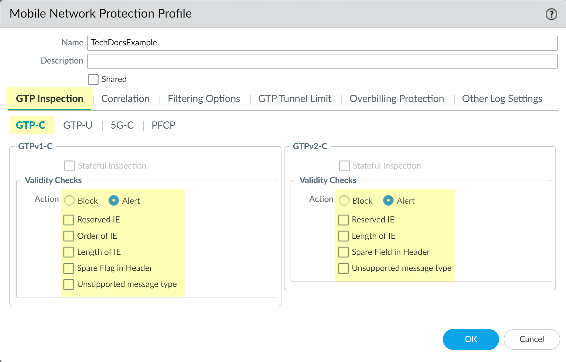
Select the GTP Inspection tab and select GTP-C if it's not already selected, then select the Validity Checks you want the firewall to perform for GTP traffic and the Action the firewall performs if the validity check isn't successful (Block or Alert). Click OK to confirm the configuration.Stateful inspection isn't available if you enable UEIP Correlation.![]() Create a Security policy to identify and allow GTP-C traffic between the MME and the serving gateway (SGW), or between the SGSN and the GCSN, depending on your deployment.There are two methods for policy creation based on the necessary level of security for GTP-C traffic. Select the appropriate method based on your security needs.
Create a Security policy to identify and allow GTP-C traffic between the MME and the serving gateway (SGW), or between the SGSN and the GCSN, depending on your deployment.There are two methods for policy creation based on the necessary level of security for GTP-C traffic. Select the appropriate method based on your security needs.- (Recommended for SGi deployments) To allow all traffic between
the MME and the SGW (or SGSN and GGSN), as well as the PGW-U or GGSN and
the Data Network zones:
- Select and Add a unique Namefor the rule in the General tab.
- In the Source tab, Add the Source Zone as Any (or all zones for S11, S5 Gn, Gi, and SGi) and the Source Address as Any.
- In the Destination tab, Add the Destination Zone as Any (or all zones for S11, S5 Gn, Gi, and SGi) and the Destination Address as Any.
- In the Application tab, Add gtpv2-c or gtpv1-c as the Application you want to allow, depending on your deployment.
- In the Service/URL Category tab, select the Serviceas Any.
- In the Actions tab, select the Action as Allow.
- Attach the Mobile Network Protection profile to the Security policy rule by selecting Profiles and selecting the profile as the Profile Type.
- Select Log at Session End if it's not already selected.
- (Recommended for S1-U deployments) To allow GTP-C application
traffic only between the MME and the SGW (or SGSN and GGSN):
- Select and Add a unique Namefor the rule in the General tab.
- In the Source tab, Add the IP address that the MME uses to communicate with the SGW (or the IP address that the MME uses to communicate with the SGW, depending on your deployment) as Source Zone and Source Address.
- In the Destination tab, Add the IP address that the MME uses to communicate with the SGW (or the IP address that the MME uses to communicate with the SGW, depending on your deployment) as the Destination Zone and Destination Address.
- In the Application tab, Add gtpv2-c or gtpv1-c as the Application you want to allow.
- In the Service/URL Category tab, select the Serviceas Any.
- In the Actions tab, select the Action as Allow.
- Attach the Mobile Network Protection profile to the Security policy rule by selecting Profiles and selecting the profile as the Profile Type.
- Select Log at Session End if it's not already selected.
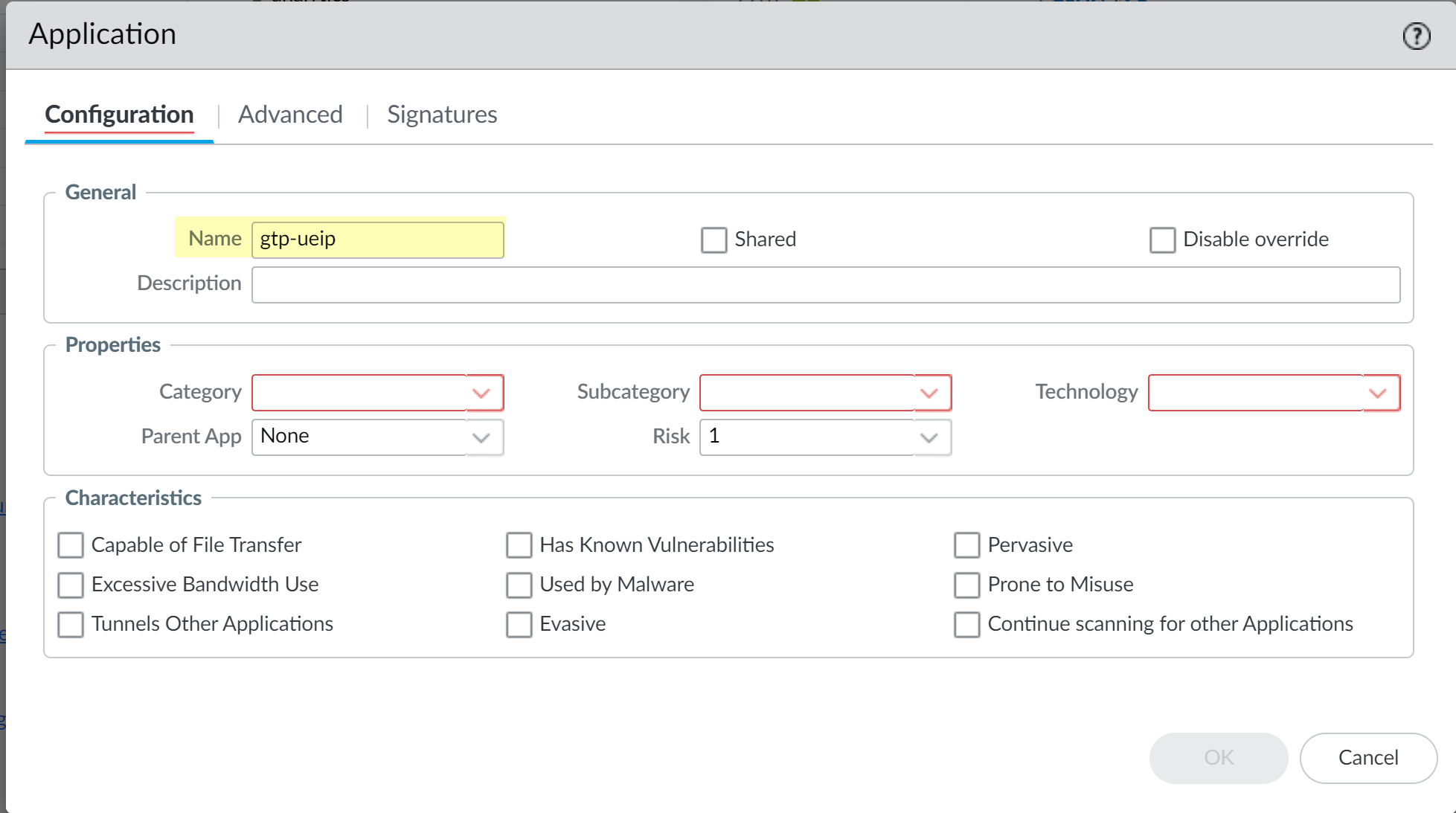
Create a custom application and a Security policy that uses the custom application. (Required if you allow traffic between only the MME and the SGW or SGSN and GGSN)Because the firewall must apply this policy rule first to process the first packet of all user traffic and enables UEIP database querying, move this policy rule above any other policy rules in your Security policy for user traffic on the N6 interface. Any application-specific IMSI or IMEI-based policy rules must occur after this policy rule.- Select and Add a unique Name for the application (for example, gtp-ueip), then click OK.
![]() Select and Add a unique Name for the policy rule.In the Source tab, Add the zone that contains traffic to the PGW-U-SGi or GGSN-U-Gi (depending on your deployment) as the Source Zone and select Any as the Source Address. If you use an IP pool for the UE IP address, add the IP pool as the Source Address .Don't select anything in the Source Subscriber or Source Equipment tabs.In the Destination tab, Add the zone that contains traffic to the Packet Data Network as the Destination Zone and select Any as the Destination Address.In the Application tab, Add the Applicationyou created in step 4.a.In the Service/URL Category tab, select Any as the Service.In the Actions tab, select Allow as the Action.Attach the Mobile Network Protection profile to the Security policy rule by selecting Profiles and selecting the profile you created in step 2 as the Profile Type.Select Log at Session Endif it's not already selected.(Recommended for S1-U deployments) Create bidirectional Security policy rules to identify and allow GTP-U application traffic on the N3 interface.
Select and Add a unique Name for the policy rule.In the Source tab, Add the zone that contains traffic to the PGW-U-SGi or GGSN-U-Gi (depending on your deployment) as the Source Zone and select Any as the Source Address. If you use an IP pool for the UE IP address, add the IP pool as the Source Address .Don't select anything in the Source Subscriber or Source Equipment tabs.In the Destination tab, Add the zone that contains traffic to the Packet Data Network as the Destination Zone and select Any as the Destination Address.In the Application tab, Add the Applicationyou created in step 4.a.In the Service/URL Category tab, select Any as the Service.In the Actions tab, select Allow as the Action.Attach the Mobile Network Protection profile to the Security policy rule by selecting Profiles and selecting the profile you created in step 2 as the Profile Type.Select Log at Session Endif it's not already selected.(Recommended for S1-U deployments) Create bidirectional Security policy rules to identify and allow GTP-U application traffic on the N3 interface.- Select and Add a unique Namefor the rule in the General tab.In the Source tab, Add the Source Zone and the Source Address of the base station and the SGW-S1-U (or the SGSN-U and GGSN-U, depending on your deployment).In the Destination tab, Add the Destination Zone and the Destination Address of the base station and the SGW-S1-U (or the SGSN-U and GGSN-U, depending on your deployment).In the Application tab, Add gtp-u as the Application you want to allow.In the Service/URL Category tab, select the Serviceas Any.In the Actions tab, select the Action as Allow.Attach the Mobile Network Protection profile to the Security policy rule by selecting Profiles and selecting the profile as the Profile Type.When the firewall identifies GTP-U traffic between the base station and the SGW-S1-U, the firewall decapsulates the inner traffic from the UE and searches for the UEIP mapping in the correlation database.Select Log at Session End if it's not already selected.(Recommended for S1U or Gn-U and SGi or Gi) deployments) Create other Security policy rules based on data (such as IP address, application, URL category, IMSI, or IMEI) to identify and allow UE traffic.If your deployment requires IP Bases Deny Rules for UE traffic in N6 deployment mode, then move the deny rule above the rule created in step 3 to ensure the Traffic logs contain the IMSI or IMEI correlation information.
- Select and Add a unique Namefor the rule in the General tab.In the Source tab, Add the Source Zone and the Source Address you want to allow. If you use an IP pool for the UE IP address, add the IP pool as the Source Address .Add the Source Subscriber and the Source Equipment you want to allow.In the Destination tab, Add the Destination Zone and the Destination Address. Select Any to allow internet access or specify the addresses of the servers in the corporate network.In the Application tab, Add as the Application types you want to allow ( for example dns, web-browsing, or SSL).In the Service/URL Category tab, select the Service types you want to allow.In the Actions tab, select the Action you want the firewall to take (Allow or Deny the traffic).Select Log at Session End if it's not already selected.(Recommended for SGi or Gi deployments if your policy allows all traffic between the MME and the SGW or SGSN and GGSN) Create a policy rule as the last rule in your policy to allow all traffic that did not match any other policy rule.Palo Alto Networks strongly recommends this step for at least the initial stages of deployment.
- Select and Add a unique Namefor the rule in the General tab.In the Source tab, Add the zone for the PGW-U-SGi (or GGSN-U-Gi) as the Source Zone. If you use an IP pool for the UE IP address, add the IP pool as the Source Address .In the Destination tab, Add the Destination Zone of the data network and the Destination Address as Any.In the Application tab, Add as the Application types as Any.In the Service/URL Category tab, select the Service type as Any.In the Actions tab, select Allow as the Action.Attach the Mobile Network Protection profile to the Security policy rule by selecting Profiles and selecting the profile as the Profile Type.Select Log at Session End if it's not already selected.Confirm that you Enabled the profile () and Commit the changes.Verify your configuration is correct.
- Verify the session traffic on the firewall logs using the following CLI commands.
- show session all filter application gtpv2-c or show session all filter application gtpv1-c
- show session all filter application gtp-u
- show session all filter source<IP address of UE>
Verify the mappings on the firewall display gtp as the source (src) using the show ueip all CLI command.View the GTP logs () and verify that the GTP Event Type displays UEIP mapping start and UEIP mapping end.Verify the UE Traffic logs () display the IMSI or IMEI in the Subscriber Identity column for the UE traffic.![]()