
PA-5540 and PA-5550
Table of Contents

PA-5540 and PA-5550
View the front, back, and top panel components and descriptions of the PA-5540 and
PA-5550 firewalls.
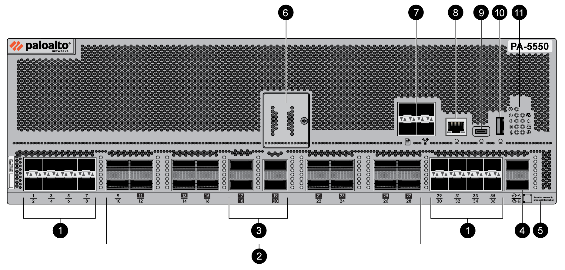
The following image shows the front panel of the PA-5540 and PA-5550
firewalls (PA-5550 pictured) and the table describes each front panel component.
|
Item
|
Component
|
Description
|
|---|---|---|
|
1
|
SFP28 Ports
|
Sixteen 10Gbps/25Gbps SFP28 ports that support SFP+ and SFP28
optics and SFP+ copper (CU) modules. SFP (1G) modules are not
supported.
The firewall has no native RJ-45 ports. |
|
2
|
QSFP28 Ports
|
Sixteen 40Gbps/100Gbps QSFP28 ports. The port numbers with a
black background indicate that the port can be broken out into
four interfaces.
|
|
3
|
QSFP-DD Ports
|
Four 40Gbps/100Gbps/400Gbps QSFP-DD ports. The port numbers with
a black background indicate that the port can be broken out into
four interfaces.
|
|
4
|
HSCI Ports
|
Each HSCI port offers 100Gbps or 400Gbps connectivity and is used
to create an Inter Firewall Link (IFL). An IFL is required to
establish NGFW clustering, which
carries configuration and state messages and data plane
traffic.
Do not assign an IP address to the HSCI port. The port carries raw Layer 1 traffic that is not routable or switchable and does not support IP addressing. Assigning an IP address to the HSCI port causes the firewall to enter a permanent suspended state. For high-throughput deployments, do not use a lower-bandwidth interface for the IFL connection. Use the HSCI port or a 100Gbps/400Gbps fiber interface to ensure sufficient bandwidth for clustering traffic. |
|
5
|
QR Code
|
A QR code that can be scanned with a mobile device to access
product documentation.
|
|
6
|
Drive Cover
|
Secures the device's drive pair, which contains PAN-OS system
files, system logs, and network traffic logs.
|
|
7
|
Management and Logging Ports
|
Management Ports
Two 1Gbps/10Gbps SFP+ management ports that are used to access
the management interface. MGT-A (active) and MGT-B (backup) are
bundled as a single logical interface called
bond0. The two bonded ports provide
redundancy, which enables the management interface to remain
active if one interface goes down. LACP is not enabled on
bond0.
The management interface is used for log forwarding by default if
you have not configured a log interface.
When using bond0 with a switch, the switch
must be configured with either a dynamic LAG setting or no LAG
setting. Configuring the switch to use a static LAG setting
causes the switch to lose connectivity. Logging Ports
Two SFP+ logging ports that offer 10Gbps connectivity each and
are used as log interfaces. LOG-1 and LOG-2 are bundled as a
single logical interface called
bond1. Bond1 uses LACP (link aggregation
control protocol) as IEEE 802.3ad. Set the
Mode for LACP status queries to
Active and the
Transmission Rate for LACP query and
response exchanges to Slow.
You must configure log
forwarding to forward logs from the log ports to one
or more log collectors. If the log interface is not configured,
the management interface is used to forward logs instead.
|
|
8
|
Console Port (RJ-45)
|
Use this port to connect a management computer to the firewall
using a 9-pin serial-to-RJ-45 cable and terminal emulation
software.
The console connection provides access to firewall boot messages,
the Maintenance Recovery Tool (MRT), and the command line
interface (CLI).
If your management computer does not
have a serial port, use a USB-to-serial converter. Use the following settings to configure your terminal emulation
software to connect to the console port:
|
|
9
|
Console port (USB-C)
|
Use this port to connect a management computer to the firewall
using a standard Type-C USB cable.
The console connection provides access to firewall boot messages,
the Maintenance Recovery Tool (MRT), and the command line
interface (CLI).
|
|
10
|
USB Port
|
A USB port that accepts a USB flash drive with a bootstrap bundle
(PAN-OS configuration).
Bootstrapping speeds
up the process of configuring and licensing the firewall to make
it operational on the network with or without internet
access.
|
|
11
|
LED Indicators
|
Nine LEDs that indicate the status of various hardware
components. For details on the LEDs, see PA-5500 Series Firewall LED Definitions.
|
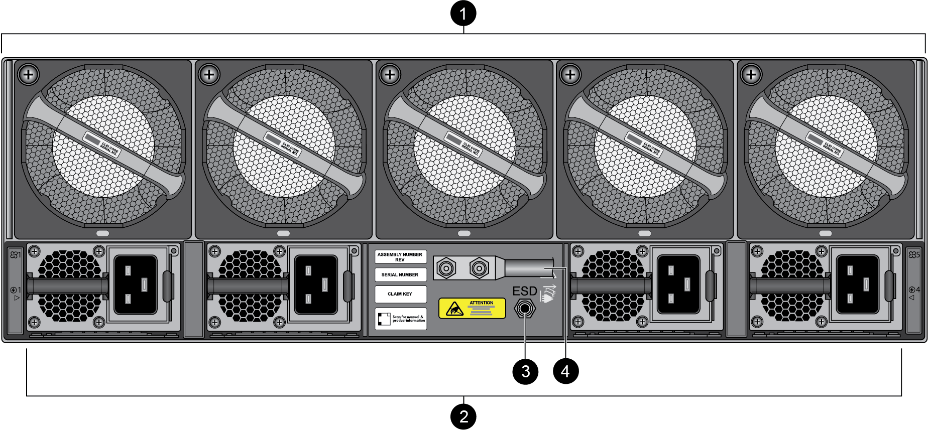
The following image shows the back panel of the PA-5540, PA-5550,
PA-5560, PA-5570, and PA-5580 firewalls and the table describes each back panel
component.
The back panel of the firewall should remain accessible to ensure ease of replacing a
power supply or fan assembly.
|
Item
|
Component
|
Description
|
|---|---|---|
|
1
|
Fan Assemblies
|
Five dual-rotor fan assemblies (for a total of ten fans) that
provide the appliance with cooling and ventilation. Each fan
assembly can be individually replaced.
The fan assemblies are numbered 1 through 5 from left to
right.
For information on replacing or installing a fan, see Replace a PA-5500 Series Firewall Fan Assembly.
|
|
2
|
Power Supplies
|
Four power supplies that provide AC or DC power to the firewall.
The number of power supplies required for operation and the
number eligible for redundancy depend on whether the power
supplies are high line, low line, or DC. The power supplies are
hot-swappable — you can replace a failed power supply without
powering off the firewall.
The power supplies are numbered 1 through 4 from left to
right.
For information on connecting power to the appliance, see Connect Power to the PA-5500 Series Firewall.
|
|
3
|
Electrostatic Discharge (ESD) port
|
Provides a grounding point that you use when removing or
installing appliance components. Secure the provided wrist strap
end of the ESD strap around your wrist and plug the other end
into the ESD port.
|
|
4
|
Ground Studs
|
Two studs used to ground the appliance to earth ground.
|
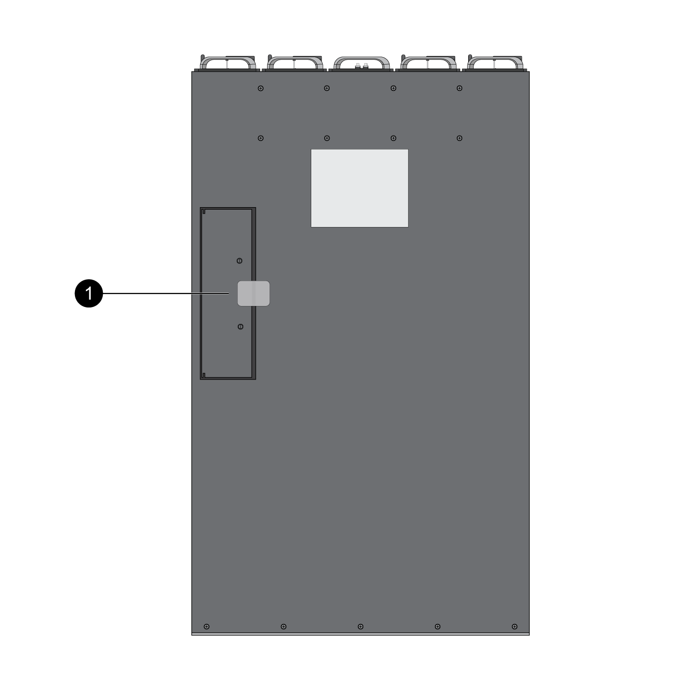
The following image shows the top panel of the PA-5540, PA-5550, PA-5560, PA-5570, and
PA-5580 firewalls (PA-5550 pictured) and the table describes each top panel
component.
|
Item
|
Component
|
Description
|
|---|---|---|
|
1
|
PCI Slot Access Hatch
|
Reserved for a future release.
|