Basic LSVPN Configuration with Static Routing
Table of Contents
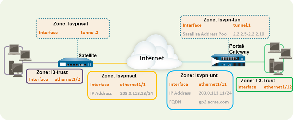
Basic LSVPN Configuration with Static Routing
This quick config shows the fastest way to
get up and running with LSVPN. In this example, a single firewall at
the corporate headquarters site is configured as both a portal and
a gateway. Satellites can be quickly and easily deployed with minimal
configuration for optimized scalability.
The
following workflow shows the steps for setting up this basic configuration:
- Configure a Layer 3 interface.In this example, the Layer 3 interface on the portal/gateway requires the following configuration:
- Interface—ethernet1/11
- Security Zone—lsvpn-tun
- IPv4—203.0.113.11/24
On the firewall(s) hosting GlobalProtect gateway(s), configure the logical tunnel interface that will terminate VPN tunnels established by the GlobalProtect satellites.To enable visibility into users and groups connecting over the VPN, enable User-ID in the zone where the VPN tunnels terminate.In this example, the Tunnel interface on the portal/gateway requires the following configuration:- Interface—tunnel.1
- Security Zone—lsvpn-tun
Create the Security policy rule to enable traffic flow between the VPN zone where the tunnel terminates (lsvpn-tun) and the trust zone where the corporate applications reside (L3-Trust).Assign an SSL/TLS Service profile to the portal/gateway. The profile must reference a self-signed server certificate.The certificate subject name must match the FQDN or IP address of the Layer 3 interface you create for the portal/gateway.- On the firewall hosting the GlobalProtect portal, create the root CA certificate for signing the certificates of the GlobalProtect components. In this example, the root CA certificate, lsvpn-CA, will be used to issue the server certificate for the portal/gateway. In addition, the portal will use this root CA certificate to sign the CSRs from the satellites.Create SSL/TLS service profiles for the GlobalProtect portal and gateways.Because the portal and gateway are on the same interface in this example, they can share an SSL/TLS Service profile that uses the same server certificate. In this example, the profile is named lsvpnserver.Create a certificate profile.In this example, the certificate profile lsvpn-profile references the root CA certificate lsvpn-CA. The gateway will use this certificate profile to authenticate satellites attempting to establish VPN tunnels.Configure an authentication profile for the portal to use if the satellite serial number is not available.
- Create one type of server profile on the portal:
- You can use RADIUS to integrate with a Multi-Factor Authentication service.
- Add an LDAP server profile. If you use LDAP to connect to Active Directory (AD), create a separate LDAP server profile for every AD domain.
Configure an authentication profile. In this example, the profile lsvpn-sat is used to authenticate satellites.Configure GlobalProtect Gateways for LSVPN.Select and Add a configuration. This example requires the following gateway configuration:- Interface—ethernet1/11
- IP Address—203.0.113.11/24
- SSL/TLS Server Profile—lsvpnserver
- Certificate Profile—lsvpn-profile
- Tunnel Interface—tunnel.1
- Primary DNS/Secondary DNS—4.2.2.1/4.2.2.2
- IP Pool—2.2.2.111-2.2.2.120
- Access Route—10.2.10.0/24
Configure the Portal.Select and Add a configuration. This example requires the following portal configuration:- Interface—ethernet1/11
- IP Address—203.0.113.11/24
- SSL/TLS Server Profile—lsvpnserver
- Authentication Profile—lsvpn-sat
Define the Satellite Configurations.On the Satellite tab in the portal configuration, Add a Satellite configuration and a Trusted Root CA and specify the CA the portal will use to issue certificates for the satellites. In this example the required settings are as following:- Gateway—203.0.113.11
- Issuing Certificate—lsvpn-CA
- Trusted Root CA—lsvpn-CA
Prepare the Satellite to Join the LSVPN.The satellite configuration in this example requires the following settings:Interface Configuration- Layer 3 interface—ethernet1/1, 203.0.113.13/24
- Tunnel interface—tunnel.2
- Zone—lsvpnsat
Root CA Certificate from Portal- lsvpn-CA
IPSec Tunnel Configuration- Tunnel Interface—tunnel.2
- Portal Address—203.0.113.11
- Interface—ethernet1/1
- Local IP Address—203.0.113.13/24
- Publish all static and connected routes to Gateway—enabled
