
PA-3530 and PA-3540
Table of Contents

PA-3530 and PA-3540
View the front, back, and top panel components and descriptions of the PA-3530 and
PA-3540 firewalls.
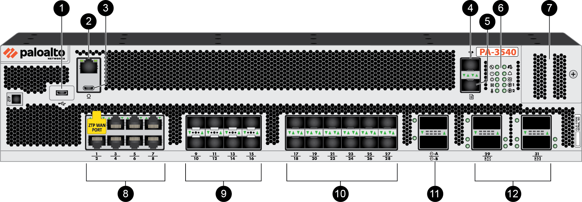
The following image shows the front panel of the PA-3530 and PA-3540
firewalls (PA-3540 pictured) and the table describes each front panel component.
|
Item
|
Component
|
Description
|
|---|---|---|
|
1
|
USB-C Port
|
One USB-C port used for debugging and administration only. Use it
to bootstrap the firewall or perform self-service enhanced
factory reset (EFR).
|
|
2
|
Console Port (RJ-45)
|
Use this port to connect a management computer to the firewall
using a 9-pin serial-to-RJ-45 cable and terminal emulation
software.
The console connection provides access to firewall boot messages,
the Maintenance Recovery Tool (MRT), and the command line
interface (CLI).
If your management computer does not
have a serial port, use a USB-to-serial converter. Use the following settings to configure your terminal emulation
software to connect to the console port:
|
|
3
|
Console port (USB-C)
|
Use this port to connect a management computer to the firewall
using a standard Type-C USB cable.
The console connection provides access to firewall boot messages,
the Maintenance Recovery Tool (MRT), and the command line
interface (CLI).
|
|
4
|
Management Port
|
One 1Gbps/10Gbps SFP+ Management port used to access the
management web interface and perform administrative tasks. The
firewall uses this port for management services, such as
retrieving licenses and updating threat and application
signatures.
|
|
5
|
Logging Port
|
One 1Gbps/10Gbps SFP+ logging port that is used as a log
interface. You must Configure Log
Forwarding to forward logs from the port to one or
more log collectors.
|
|
6
|
LED Indicators
|
Ten LEDs that indicate the status of various hardware components.
For details on the LEDs, see PA-3500 Series Firewall LED Definitions.
|
|
7
|
SSD Cover
|
Secures the device's SSD, which contains PAN-OS system files,
system logs, and network traffic logs.
|
|
8
|
Copper RJ-45 Ports
|
Eight 1Gbps/2.5Gbps/5Gbps/10Gbps RJ-45 ports. Port 1 is used for
Zero Touch
Provisioning (ZTP).
|
|
9
|
SFP28 Ports
|
Eight 25Gbps SFP28 ports.
|
|
10
|
SFP/SFP+ Ports
|
Twelve 1Gbps/10Gbps SFP/SFP+ ports.
|
|
11
|
HSCI Ports
|
Two HSCI ports that offer 40Gbps/100Gbps connectivity and are
used to connect two firewalls in a high availability (HA)
Active/Passive configuration. This port is for HA1 (control) and
HA2 (data link).
|
|
12
|
QSFP28 Ports
|
Four 40Gbps/100Gbps QSFP28 ports. Ports 30 and 32 support breakout
into four 10Gbps/25Gbps interfaces each: port 30 breaks out into
ports 33–36 and port 32 breaks out into ports 35–38. Ports 29 and
31 do not support breakout.
|
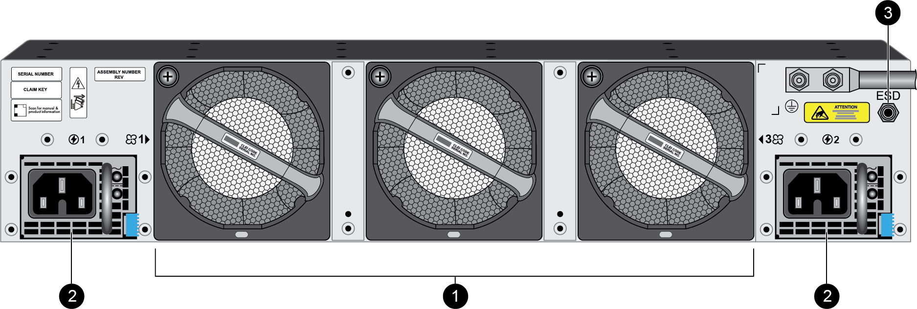
The following image shows the back panel of the PA-3530 and PA-3540
firewalls (PA-3540 pictured) and the table describes each back panel component.
The back panel of the firewall should remain accessible to ensure ease of replacing a
power supply or fan assembly.
|
Item
|
Component
|
Description
|
|---|---|---|
|
1
|
Fan Assemblies
|
Three dual-rotor fan assemblies (for a total of six fans) that
provide the appliance with cooling and ventilation. Each fan
assembly can be individually replaced.
The fan assemblies are numbered 1 through 3 from left to
right.
For information on replacing or installing a fan assembly, see
Replace a PA-3500 Series Firewall Fan Assembly.
The firewall is designed to continue
operating even if one fan rotor has failed. |
|
3
|
Ground Stud
|
A stud used to ground the appliance to earth ground.
|
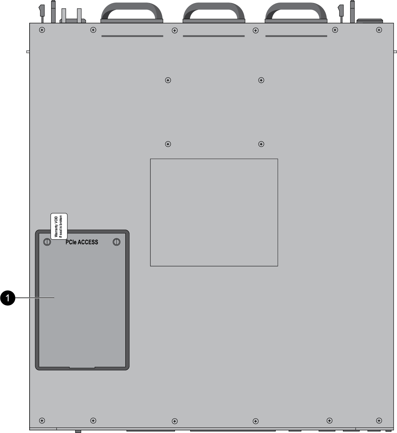
The following image shows the top panel of the PA-3500 Series
firewalls and the table describes each top panel component.
|
Item
|
Component
|
Description
|
|---|---|---|
|
1
|
PCI Slot Access Hatch
|
Reserved for a future release.
|