Install the PA-7500 Series Firewall in an Equipment Rack
Table of Contents
Install the PA-7500 Series Firewall in an Equipment Rack
Learn how to install the PA-7500 Series Firewall using a rack mount kit.
The following procedure describes how to install the PA-7500 Series firewall in an
equipment rack.
The PA-7500 chassis and the interface cards (MPC, NPC, DPC, and SFC) ship in
separate boxes and it is recommended that you install the cards after you
rack-mount the appliance. This will prevent any damage to the cards that could
occur during rack mounting and will reduce the weight of the appliance. To
further reduce the weight, remove the fan assemblies and power supplies. The
PA-7500 requires 14 RU (rack units) of rack space. Unless specified, screws are
not provided.
Read the following safety information before you proceed:
- Elevated ambient operating temperature—If the PA-7500 Series firewall is installed in a closed or multi-unit rack assembly, the ambient operating temperature of the rack environment may be greater than the ambient room temperature. Verify that the ambient temperature of the rack assembly does not exceed the maximum rated ambient temperature requirements listed in PA-7500 Series Firewall Environmental Specifications.
- Reduced airflow—Ensure that the airflow required for safe operation is not compromised by the rack installation.
- Mechanical loading—Ensure that the rack-mounted firewall does not cause hazardous conditions due to uneven mechanical loading.
- Circuit overloading—Ensure that the circuit that supplies power to the firewall is sufficiently rated to avoid circuit overloading or excess load on supply wiring. See PA-7500 Series Firewall Electrical Specifications.
- Reliable earthing—Maintain reliable earthing of rack-mounted equipment. Pay special attention to power connections other than direct connections to the branch circuit (such as use of power strips or extension cords) to ensure that the firewall does not exceed power ratings for connected hardware.
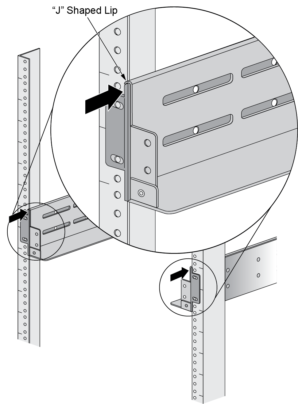
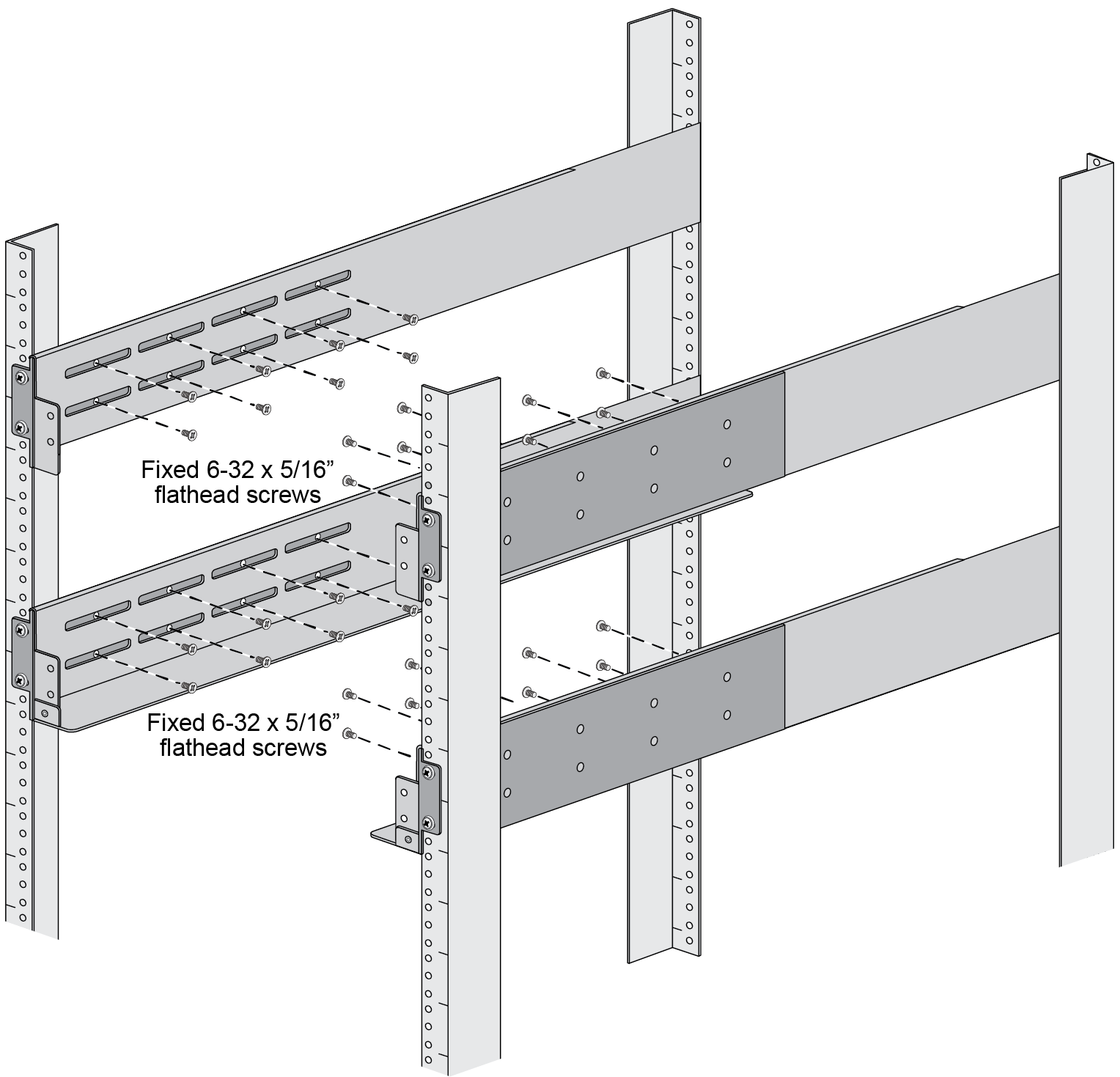
- Slide one of the adjustable mounting brackets into the “J” shaped lip on the top edge of one of the fixed mounting brackets. Repeat with the second adjustable and fixed mounting brackets.
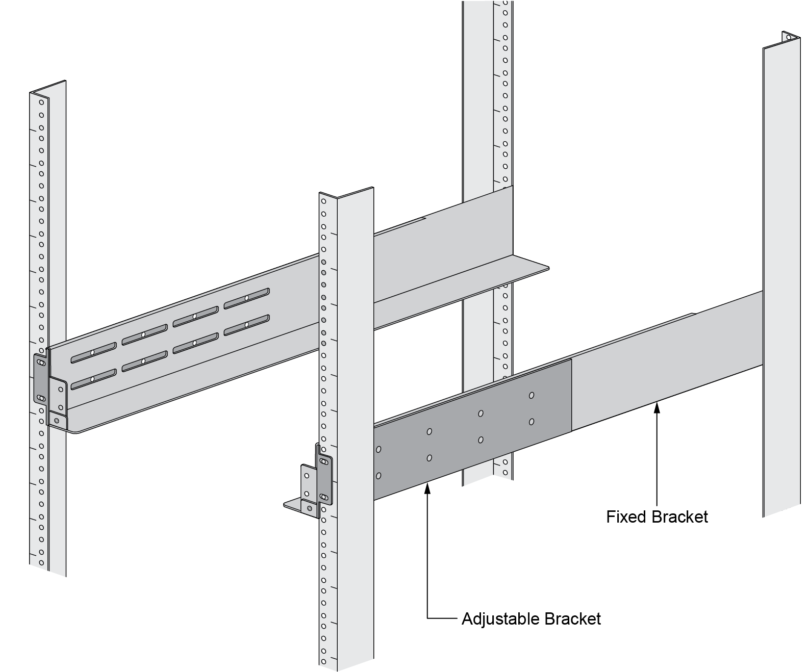
![]() Position the bottom edges of the fixed and adjustable brackets to the bottom of the 14 RU rack space reserved for the PA-7500. Align the slotted holes of the fixed mounting bracket to the holes on the front side of the equipment frame being used. Similarly, align the slotted holes in the adjustable mounting bracket to the holes on the rear of the equipment frame.
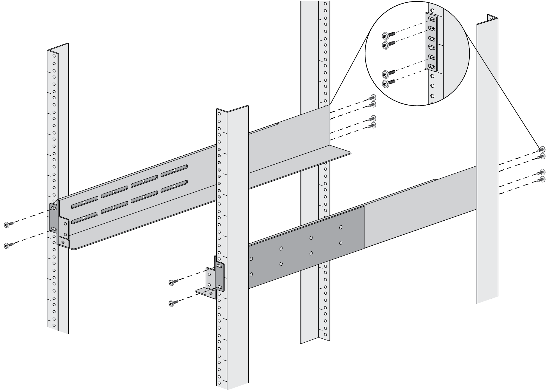
Position the bottom edges of the fixed and adjustable brackets to the bottom of the 14 RU rack space reserved for the PA-7500. Align the slotted holes of the fixed mounting bracket to the holes on the front side of the equipment frame being used. Similarly, align the slotted holes in the adjustable mounting bracket to the holes on the rear of the equipment frame.![]() Adjust the brackets to fit the depth of the equipment frame, then secure the brackets to the equipment frame with mounting screws (not provided) compatible with your equipment frame. Tighten the screws to their recommended torque value.The mounting brackets are designed for equipment frames that are up to 32” deep (81.3 cm).
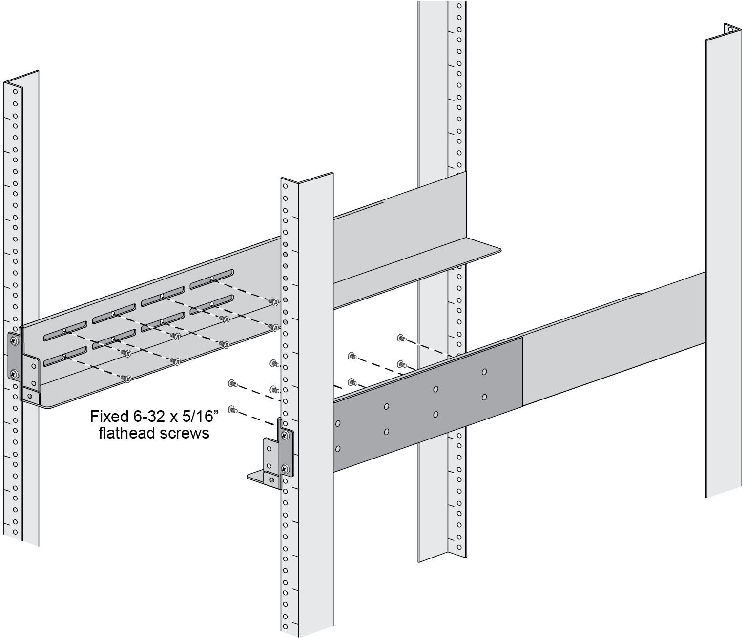
Adjust the brackets to fit the depth of the equipment frame, then secure the brackets to the equipment frame with mounting screws (not provided) compatible with your equipment frame. Tighten the screws to their recommended torque value.The mounting brackets are designed for equipment frames that are up to 32” deep (81.3 cm).![]() Use the provided 6-32 x 5/16 flathead screws to secure the adjustable bracket to the fixed bracket. A minimum of 6 screws are required for each side.
Use the provided 6-32 x 5/16 flathead screws to secure the adjustable bracket to the fixed bracket. A minimum of 6 screws are required for each side.![]() Repeat Steps 1 through 4 for the mid and top mount brackets.
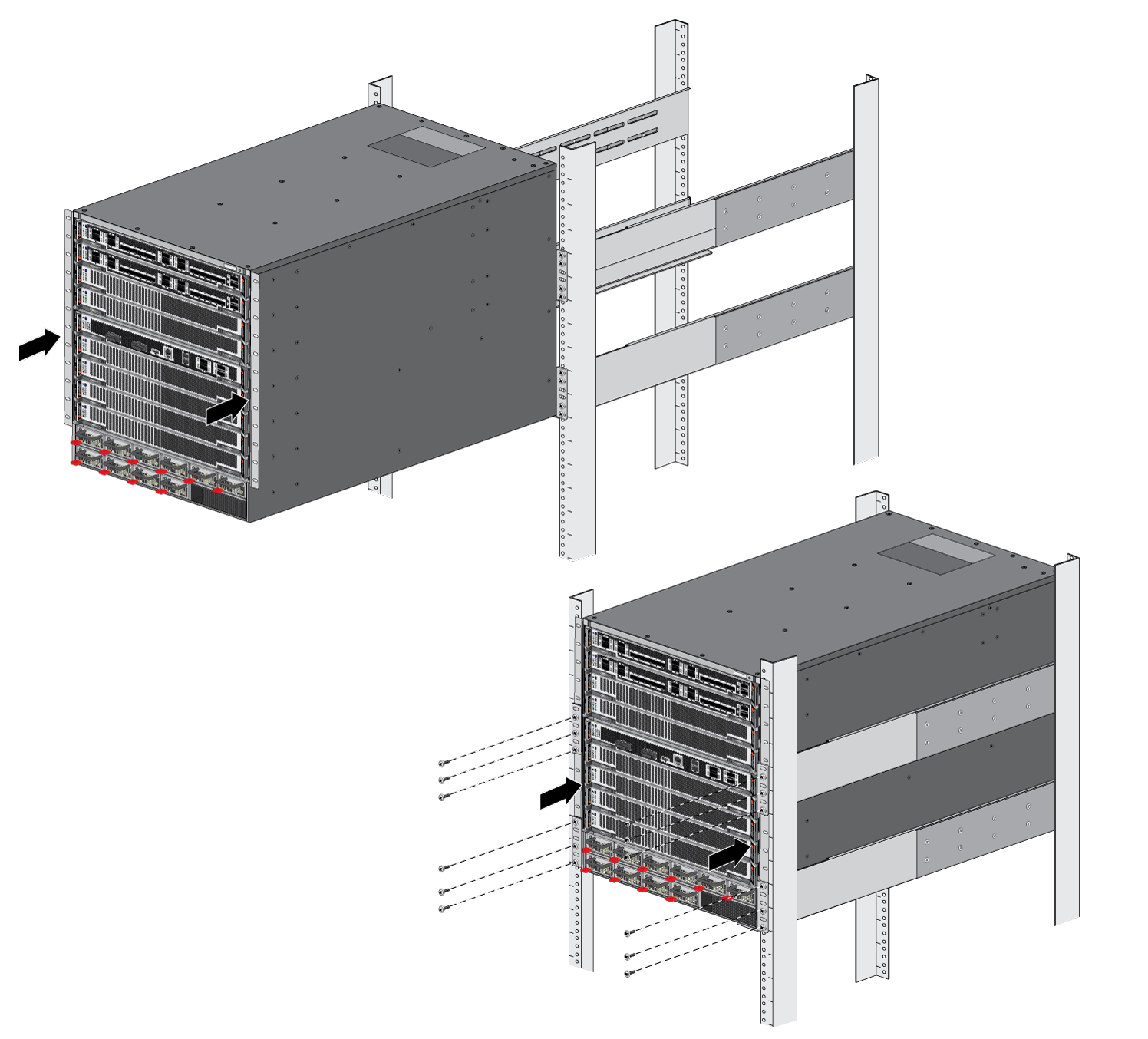
Repeat Steps 1 through 4 for the mid and top mount brackets.![]() Slide the PA-7500 on the brackets that were previously mounted to the equipment frame until the front mounting flanges of the PA-7500 are flush against the mounting surface of the equipment frame.Secure the PA-7500 to the equipment frame on both sides using 8 screws per bracket (not provided). The screws must be compatible with your equipment frame.
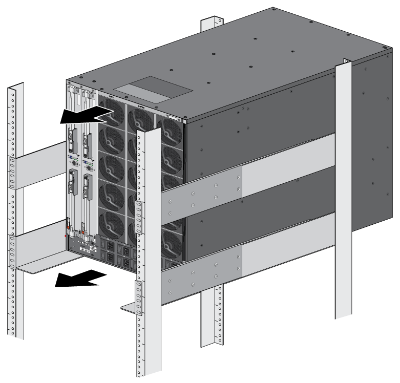
Slide the PA-7500 on the brackets that were previously mounted to the equipment frame until the front mounting flanges of the PA-7500 are flush against the mounting surface of the equipment frame.Secure the PA-7500 to the equipment frame on both sides using 8 screws per bracket (not provided). The screws must be compatible with your equipment frame.![]() Use the provided 8-32 x 3/8” Phillips panhead screws to secure the back side of the PA-7500 to the previously mounted brackets.
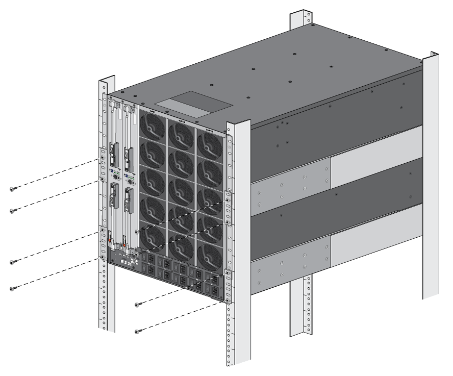
Use the provided 8-32 x 3/8” Phillips panhead screws to secure the back side of the PA-7500 to the previously mounted brackets.![]()
![]()