Replace a PA-7500 Series Firewall Fan Assembly
Table of Contents
Replace a PA-7500 Series Firewall Fan Assembly
Learn how to replace a fan assembly on a PA-7500 Series firewall.
The PA-7500 Series firewall can support up to fifteen dual-rotor, single fan
assemblies on its rear side. Each single fan assembly can be individually removed
and replaced. When a fan is functioning as expected, the LED on the fan assembly
will be green. If a fan fails, the fault LED on the fan assembly will turn red. If
this occurs, replace the fan immediately to avoid service interruption. If two or
more fans fail, the firewall shuts down.
You can replace a failed fan assembly while the firewall is powered on; however,
you must use the CLI to view the non-failed fan speeds to assess how much time
you have before the thermal protection circuit automatically shuts down the
firewall. Issue the following command to check the speed of the fans that you
are not replacing:
admin@PA-7500> show system environmentals fansIf the non-failed fans are operating at less than 12,000 RPM, there is no
absolute time limit to replace the fan assembly.
If the non-failed fans are operating at 12,000 RPM or higher, or if there are two
or more fans missing, there is a time limit of 120 seconds starting when the fan
assembly is removed to replace it before the thermal protection circuit
automatically powers down the firewall.
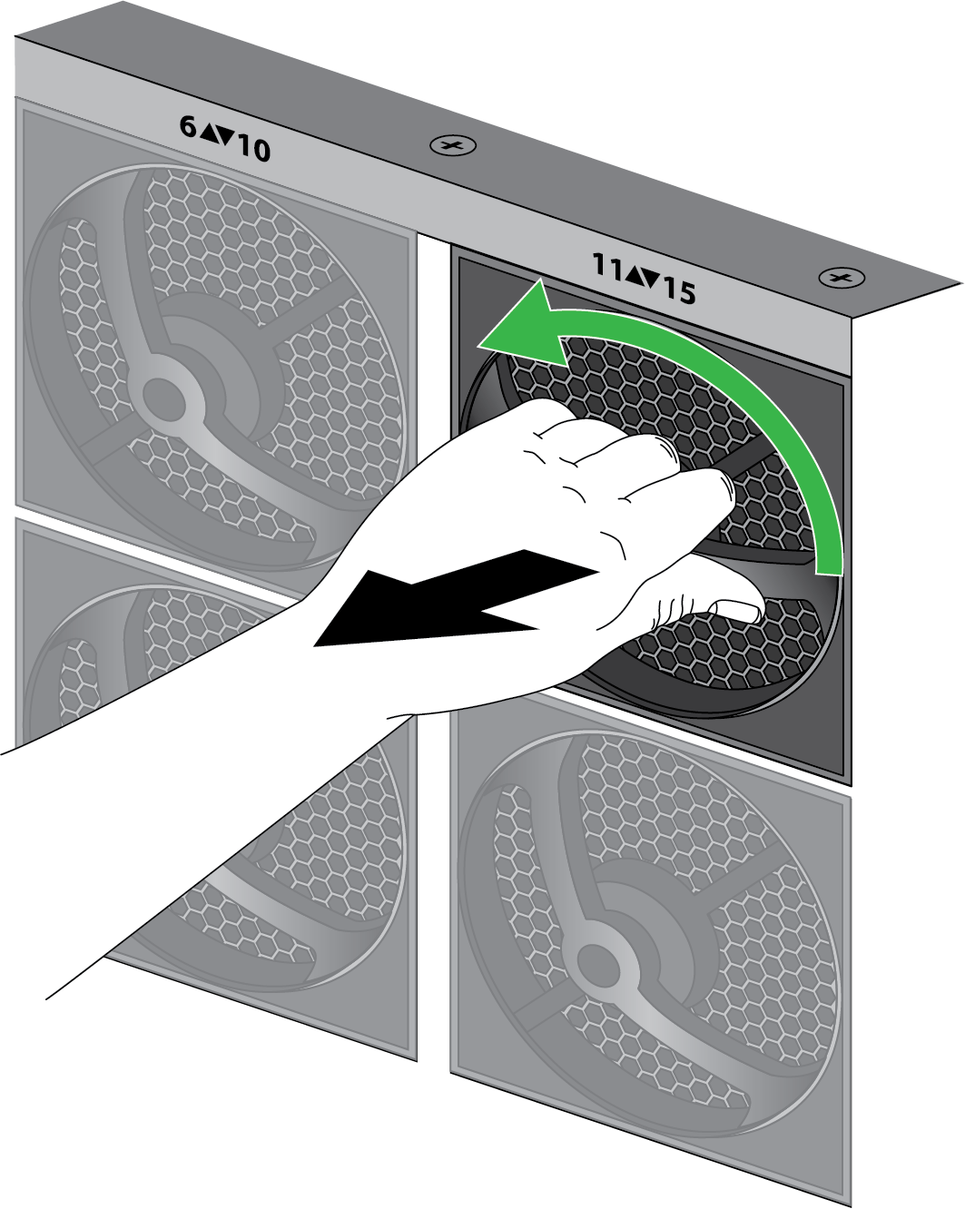
- Put the provided ESD wrist strap on your wrist ensuring that the metal contact is touching your skin. Then attach (snap) one end of the ground cable to the wrist strap and remove the alligator clip from the banana clip on the other end of the ESD grounding cable. Plug the banana clip end into the ESD port located on the appliance before handling ESD sensitive hardware.When removing a fan assembly, first pull the fan assembly out about 1 inch (2.5cm) and wait 10 seconds. This allows enough time for the working fans to stop spinning.Remove the replacement fan assembly from the packaging and have it ready.Identify the failed fan assembly by checking the fault LEDs of each fan. In the event of a failure, the LED on the fan assembly will be red.Grip the failed fan assembly by the handle and turn it to the left. Gently pull the fan assembly out of its slot.
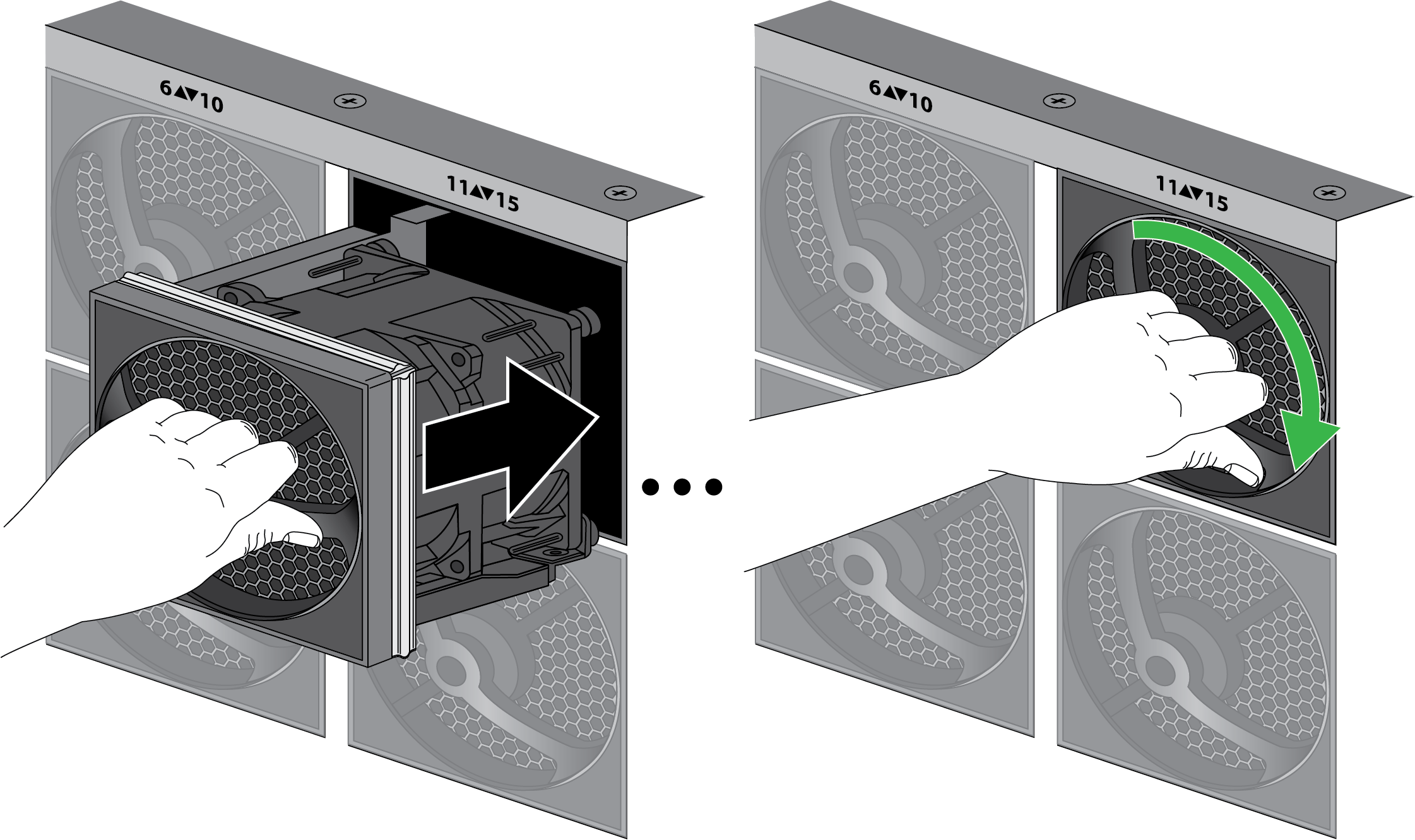
![]() Install the replacement fan by sliding it into the vacant fan slot. Turn the handle to the right to secure the fan assembly in place.
Install the replacement fan by sliding it into the vacant fan slot. Turn the handle to the right to secure the fan assembly in place.![]() Verify that the new fan assembly is operational by noting the status of the fan assembly LED and the fan LED on the Management Processing Card (MPC). The individual fan assembly LED shows green if it is functioning as expected. Similarly, the fan LED on the MPC also shows green if all fans are working as expected. You can also view the status of the fan trays by entering the following command:
Verify that the new fan assembly is operational by noting the status of the fan assembly LED and the fan LED on the Management Processing Card (MPC). The individual fan assembly LED shows green if it is functioning as expected. Similarly, the fan LED on the MPC also shows green if all fans are working as expected. You can also view the status of the fan trays by entering the following command:admin@PA-7500> show system environmentals fan-trayTo view the status of each fan on a fan tray, run the following command:admin@PA-7500> show system environmentals fans