SD-WAN
SD-WAN Deployment Workflow
Table of Contents
SD-WAN Deployment Workflow
Overall step-by-step procedure for your SD-WAN deployment.
| Where Can I Use This? | What Do I Need? |
|---|---|
|
|
(Panorama Only) Key SD-WAN deployment steps:
After you plan your SD-WAN configuration, install the
SD-WAN plugin and set up the Panorama™ management server to centrally manage the SD-WAN
configuration of your hub and branch firewalls. By leveraging Panorama, you reduce
management requirements and operational overhead for administering your SD-WAN
deployment and can more easily monitor link health and troubleshoot issues should they
arise.
- Plan the SD-WAN architecture and install the necessary plugin. Acquire the Advanced SD-WAN license and validate SD-WAN interface setup on vsys1 (for multi-vsys firewalls).
- Onboard firewalls to Panorama and define base templates and device groups: Configure link tags, SD-WAN interface profiles, and traffic distribution/path quality profiles. Establish required security zones (internal, branch, hub) and define SD-WAN policy rules.
- Configure the interfaces, SD-WAN policy rules, and SD-WAN link management profiles.
- Add firewalls as hub or branch devices and a VPN Cluster to define the topology (hub-and-spoke or mesh).
(Strata Cloud Manager Only) Key SD-WAN deployment steps:
- Plan the SD-WAN architecture. You do not need to install any plugin if you are using the Strata Cloud Manager. Acquire the Advanced SD-WAN license and validate SD-WAN interface setup on vsys1 (for multi-vsys firewalls).
- Enable Cloud Management and onboard/activate firewalls and licenses using Strata Cloud Manager.
- Organize firewalls into separate hubs and branch folders/snippets.
- The SD-WAN plugin will automatically create the zones.
- Configure the interfaces, SD-WAN policy rules, BGP distribution profiles, SD-WAN link management profiles, and VPN Cluster.
- If Panorama or Strata Cloud Manager is managing a multi-vsys firewall, all SD-WAN enabled interfaces and configurations must be configured on vsys1.
- SD-WAN does not support an SD-WAN configuration across multiple virtual systems of a multi-vsys firewall.
- You need an Advanced SD-WAN license to enable the SD-WAN feature in the Palo Alto Networks firewalls.
PAN-OS & Panorama
Set up and configure SD-WAN on PAN-OS & Panorama for Palo Alto
Networks Next-Generation Firewalls.
The following list is a preview of the configuration tasks you need to
perform to prepare for your SD-WAN deployment. The detailed steps for
you to take to accomplish each task appear in subsequent task topics.
- Onboard the firewall to the Panorama management server either manually or using ZTP. Create basic device groups and templates.Create link tags. Link tags enable you to identify common link types and link it with the SD-WAN interface profiles. They are free form entries that are referenced in multiple locations. Be consistent and meaningful when creating the link tags.Create an SD-WAN interface profile to define the link type, link tag, upload and download bandwidth speed of the link, and path monitoring link types (aggressive or relaxed).Enable SD-WAN in Ethernet, sub Ethernet, and Aggregated Ethernet Interfaces; then add the next hop gateway and apply the SD-WAN interface profile.As part of your SD-WAN policy, you use SD-WAN traffic distribution profiles to assign which traffic distribution method the path-selection algorithm uses for an application. The path-selection algorithm uses the path metrics, thresholds, and sensitivities as defined in a path quality profile.(Optional) Each SD-WAN path quality profile (PQP) consists of a set of ranked metrics and thresholds that an application requires for optimal performance. There are predefined PQPs or you can also create custom PQPs.Create zone-internal, zone-to-branch, and zone-to-hub security zones (case sensitive). The SD-WAN plugin will create these zones, but the best practice is to preprovision these zones so they can be added to existing Security policy rules (prior to SD-WAN transition). Every transport or interface participating in SD-WAN needs to be in the same security zone.Define the SD-WAN policy rules. SD-WAN policies are similar to security policy rules. You can also apply Path Quality Profiles and Traffic Distribution Profiles in the SD-WAN policy rules.After completing the above steps, follow this workflow to complete your SD-WAN deployment using the SD-WAN plugin.Add the Palo Alto Networks firewall as an SD-WAN hub or a branch device to the SD-WAN plugin.Create a VPN Cluster with the appropriate cluster type (hub and spoke or mesh) based on your network topology requirement. Then add the branches and hubs to your selected topology.
Strata Cloud Manager
Set up and configure SD-WAN on Strata Cloud Manager for Palo Alto Networks Next-Generation Firewalls.Contact your account team to enable Cloud Management for NGFWs using Strata Cloud Manager.Set Up SD-WAN
Set up a Software-Defined Wide Area Network (SD-WAN) on Strata Cloud Manager for your Palo Alto Networks Next-Gen Firewalls (NGFW).- Log in to Strata Cloud Manager.Onboard your SD-WAN firewalls to Strata Cloud Manager.All newly added firewalls are added the All Firewalls folder by default.Activate the SD-WAN license on your firewall.Create the SD-WAN folders for hub and branch firewalls.Separate folders for your hub and branch firewalls are required to containing all SD-WAN configuration objects specific to hub and branch firewall deployments.
- Select and Add Folder.Add new folders for your hub and branch SD-WAN firewalls.In Folder Management, locate your hub and branch firewalls and expand the Actions menu to Move your firewalls.For the Destination, select the hub or branch folder you created and Move.Create zone-internal, zone-to-branch, and zone-to-hub security zones (case sensitive). The SD-WAN plugin will create these zones, but the best practice is to preprovision these zones so they can be added to existing Security policy rules (prior to SD-WAN transition). Every transport or interface participating in SD-WAN needs to be in the same security zone.Create link tags.Create a link tag to identify one or more physical links that you want applications and services to use in a specific ordering during SD-WAN traffic distribution and failover protection. Grouping multiple physical links allows you to maximize the application service quality if the physical link health deteriorates.
- Select and create your link tags at the All Firewalls Context Scope.Palo Alto Networks recommends creating all link tags at the All Firewalls folder level to ensure link tags are available to all SD-WAN firewalls regardless of the folder they’re associated with.Add Tag.Enter a Name and select a Color to identify the link tag.Save.
Configure SD-WAN
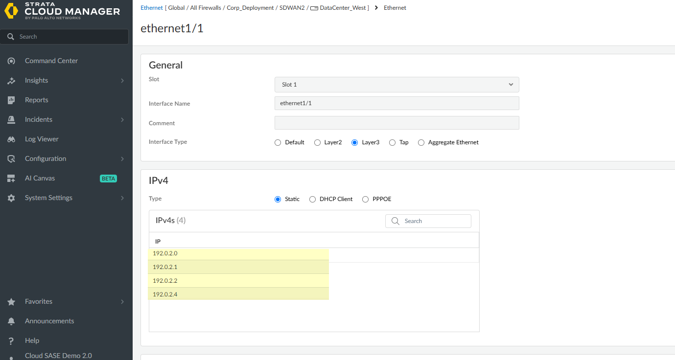
Contact your account team to enable Cloud Management for NGFWs using Strata Cloud Manager.Configure the physical Ethernet interfaces and SD-WAN interface profile to enable SD-WAN functionality and define the characteristics of the ISP connections the firewall monitors. Additionally, you must create the SD-WAN VPN cluster to determine which branches communicate with which hubs and to create a secure connection between the branch and hub firewalls.- Log in to Strata Cloud Manager.Set up SD-WAN.Configure a layer 3 interface.Layer 3 interfaces are required for SD-WAN functionality. Repeat this step to configure as many Layer 3 Ethernet interfaces on your SD-WAN firewall as needed.You can configure up to four IP addresses for an SD-WAN enabled interface. The Auto VPN workflows uses only the first IP address from the configured IPv4 address list to create the VPN tunnel and ignores the remaining IPv4 addresses in the list.
![]() Configure a logical router and add the interfaces that you created in the previous step to the logical router.(Optional) Configure a BGP redistribution profile.Configure an SD-WAN interface profile.The SD-WAN interface profile defines the characteristics of the ISP connection, specifies the speed of links and how frequently the firewall monitors the link, and specifies the link tag. When you specify the same Link Tag on multiple links, you’re grouping (bundling) those physical links into a link bundle or fat pipe.
Configure a logical router and add the interfaces that you created in the previous step to the logical router.(Optional) Configure a BGP redistribution profile.Configure an SD-WAN interface profile.The SD-WAN interface profile defines the characteristics of the ISP connection, specifies the speed of links and how frequently the firewall monitors the link, and specifies the link tag. When you specify the same Link Tag on multiple links, you’re grouping (bundling) those physical links into a link bundle or fat pipe.- Select and select the hub or branch folder where want to create the SD-WAN interface profile.Add Profile.Enter a descriptive Name for the profile.Select the Link Tag the profile assigns to the interface.Select the Link Type from the predefined list.Specify the Maximum Download (Mbps) speed from the ISP.Specify the Maximum Upload (Mbps) speed to the ISP.Check (enable Eligible for Error Correction Profile Interface Selection to enable Forward Error Correction (FEC) or packet duplication for interfaces.If enabled, you must enable this setting for both sending and receiving firewalls.VPN Data Tunnel Support determines whether the branch-to-hub traffic and return traffic flows through a VPN tunnel for added security or flows outside of the VPN tunnel to avoid encryption overhead. This setting is enabled by default.
- Keep enabled for public links that have direct internet connections or internet break capabilities, such as cable modem, ADSL, and other internet connections.
- Disable for private link types such as MPLS, satellite, or microwave that doesn’t have internet breakout capability. However, you must first ensure that the traffic can’t be intercepted because it will be sent outside of the VPN tunnel.
- The branch might have DIA traffic that needs to fail over to the private MPLS link connecting to the hub, and reach the internet from the hub. The VPN Data Tunnel Support setting determines whether the private data flows through the VPN tunnel or flows outside the tunnel, and the failed over traffic uses the other connection (that the private data flow doesn’t use). The firewall uses zones to segment DIA failover traffic from private MPLS traffic.
Set the VPN Failover Metric if DIA AnyPath is enabled a hub or branch firewall, to prioritize the order in which a particular hub is selected for failover.The lower the metric, the higher the priority of the interface to be selected during failover. If multiple hub virtual interfaces have the same metric value, SD-WAN sends new session traffic to them in round-robin fashion.Select the Path Monitoring mode.- Aggressive—Firewall sends probe packets to the opposite end of the SD-WAN link at a constant frequency. Use this mode if you need fast detection and failover for brownout and blackout conditions. Default for all link types except LTE and Satellite.
- Relaxed—Firewall waits for a number of seconds (Probe Idle Time) between sending sets of probe packets, making path monitoring less frequent. When the probe idle time expires, firewall sends probes for 7 seconds at the Probe Frequency configured. Use this mode when you have low-bandwidth links, links that charge by usage (such as LTE), or when fast detection isn’t as important as preserving cost and bandwidth. Default for LTE and Satellite link types.
Set the Probe Frequency (per second) to specify the number of times per second the firewall sends a probe packet to the opposite end of the SD-WAN link. The default setting provides subsecond detection of brownout and blackout conditions.Set the Probe Idle Time (seconds) to specify how long the firewall waits between sets of probe packets.Set the Failback Hold Time (seconds) to specify how long the firewall waits for a recovered link to remain qualified before the firewall reinstates the link after it has failed.Save.Configure a VPN cluster for your hub and branch firewalls.- Select and Add VPN Cluster.Check (enable) SD-WAN.Add the hub firewalls to the VPN cluster.
- Add Hub Devices to select one or more firewalls to Add as hubs.Up to four hubs are supported for a VPN cluster.
- Click the firewall in the Hub Devices list.
- Set the hub firewall Priority.Range is 1 to 4. The lower the priority value, the higher the priority and local preference. A cluster supports a maximum of four hubs. An active/passive HA pair counts as one hub. Multiple hubs can have the same priority; an HA pair must have the same priority.
- Select a Logical Router.
- (Optional) Check (enable) DIA VPN and select a DIA VPN Link Tag.
- Update.
- Repeat this step for all hub firewalls that you add to the VPN cluster.
Add the branch firewalls to the VPN cluster.- Add Hub Devices to select one or more firewalls to Add as hubs.
- Select a Logical Router.
- (Optional) Select a BGP Redistribution Profile.
- Update.
- Repeat this step for all branch firewalls that you add to the VPN cluster.