SD-WAN
Configure Ethernet Interface for SD-WAN
Table of Contents
Configure Ethernet Interface for SD-WAN
Configure Ethernet Layer 3 interfaces with SD-WAN
functionality.
| Where Can I Use This? | What Do I Need? |
|---|---|
|
|
In Panorama, configure a physical, Layer 3 Ethernet interface and enable SD-WAN functionality. To configure a physical interface, you must
assign it an IPv4, or IPv6 address (SD-WAN plugin 3.2.0 and later
versions), or both. You must also assign the interface a fully qualified
next-hop gateway and assign an SD-WAN interface profile to the interface. SD-WAN supports only a Layer 3 interface type; it doesn't support
Layer 2 networks such as
VPLS. The SD-WAN interface profile defines key characteristics that the
firewall uses to manage that specific physical link, such as the link type (ADSL,
cable modem, MPLS), maximum upload and download speeds, and path monitoring
settings. By associating an SD-WAN interface profile with a physical
Ethernet interface, you're essentially telling the firewall how to treat that
specific connection within the SD-WAN environment. This association
allows the firewall to apply the appropriate settings for link management, failover
behavior, and traffic routing based on the profile's
configuration.
After you use Panorama to create a VPN cluster and export your hub and
branch information in the CSV, an Auto VPN configuration in the SD-WAN plugin uses this information to generate a configuration for the associated
branches and hubs that includes the predefined SD-WAN zones and
creates secure VPN tunnels between SD-WAN branches and hubs. Auto VPN
configuration also generates the BGP configuration if you enter BGP information in
the CSV or in Panorama when you add an SD-WAN branch or
hub.
PAN-OS & Panorama
Configure Ethernet Layer 3 interfaces with SD-WAN functionality in
PAN-OS.
- Select , select the appropriate template from the Template context drop-down, select a slot number, such as Slot1, and select an interface (for example, ethernet1/1).
- Select the Interface Type as Layer3.
- On the Config tab, for a legacy routing engine, select a Virtual Router or create a new virtual router. For Advanced Routing Engine, select a Logical Router or create a new logical router.
- Assign the Security Zone that is appropriate for the interface you’re configuring.For example, if you’re creating an uplink to an ISP, you must know that the Ethernet interface you chose is going to an untrusted zone.
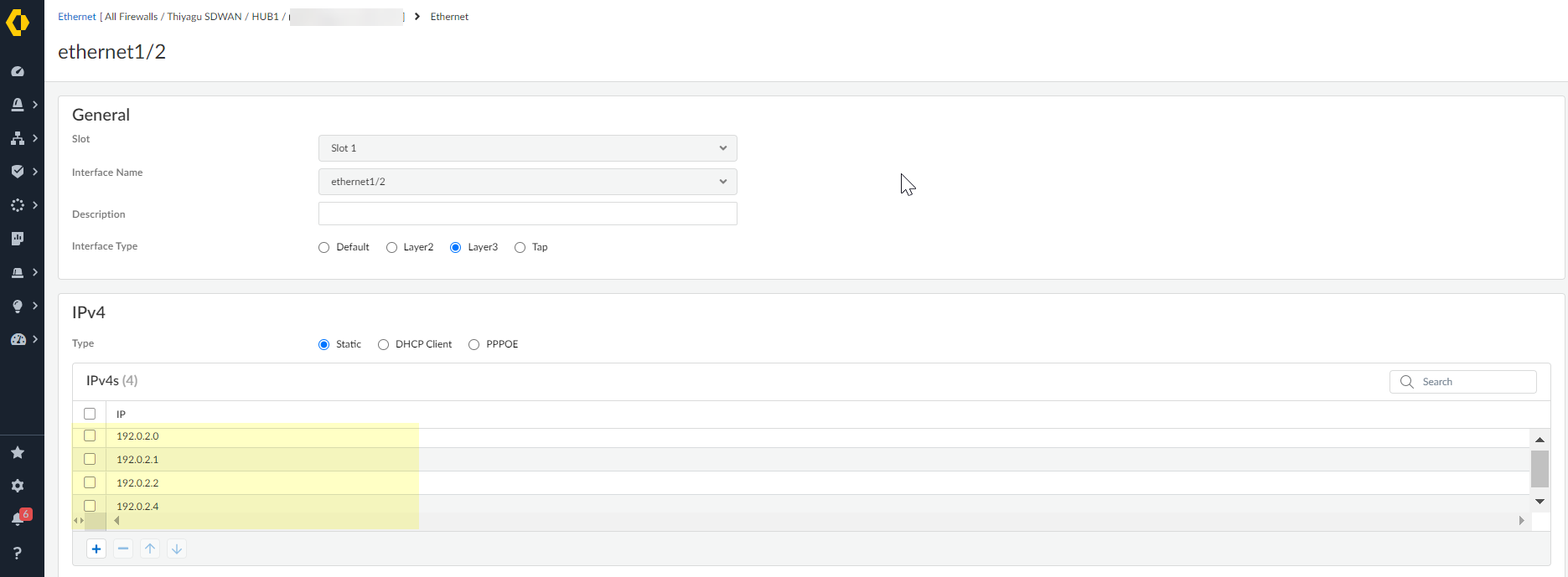
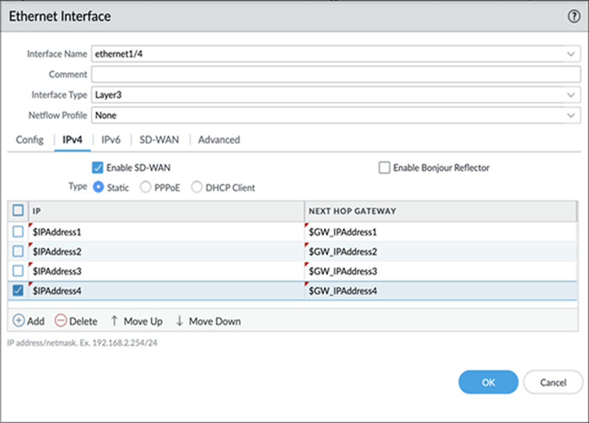
- To enable SD-WAN on an IPv4 interface, select the IPv4 tab and Enable SD-WAN.With SD-WAN plugin 3.2.0 and later releases, you can configure up to four IP addresses for an SD-WAN enabled interface. The SD-WAN plugin uses only the first IP Address from the configured IP address list to create the SD-WAN tunnel.The SD-WAN considers only the first IP address for the Next Hop Gateway and ignores the remaining IP addresses in the list.(HA deployments only) If you wish to downgrade from SD-WAN plugin version 3.2.0 to 3.1.0 or earlier, remove the HA active/passive configurations on both the firewalls before attempting a downgrade procedure, such as downgrading PAN-OS and SD-WAN plugin versions.
- For an IPv4 interface, select Type of address:
- Static—In the IP field, Add an IPv4 address and prefix length for the interface. You can use a defined variable, such as $uplink, with a range of addresses. Note that you can only add an IPv4 address or a defined variable and not an address object for the IP field. Enter the fully qualified IPv4 address of the Next Hop Gateway (the next hop from the IPv4 address you just entered). The Next Hop Gateway must be on the same subnet as the IPv4 address. The Next Hop Gateway is the IP address of the ISP’s default router that the ISP gave you when you bought the service. It is the next hop IP address to which the firewall sends traffic to reach the ISP’s network, and ultimately, the internet and the hub.
- (PAN-OS 9.1.2 and later releases, and SD-WAN Plugin 1.0.2 and later releases) PPPoE—Enable PPPoE authentication for DSL links, enter the Username and Password, and Confirm Password.
- DHCP Client—It’s critical that DHCP assigns a
default gateway, also known as the next hop gateway for the ISP
connection. The ISP will provide all the necessary connectivity
information, such as dynamic IP address, DNS servers, and the default
gateway. Although DHCP Client is supported for a hub or branch interface, on a hub interface it’s preferable for you to assign a Static address instead of DHCP Client. Using DHCP on a hub requires the Palo Alto Networks DDNS service. Using a Static address at the hub site creates a more stable environment because DDNS isn’t involved when resolving the DHCP IP address changes, and because the DDNS service can take a few minutes to register the new IP address when it changes. If you have multiple branch sites connecting to a hub site, having stability is critical to keeping the network up and running.If you select DHCP Client, be sure to disable the option Automatically create default route pointing to default gateway provided by server, which is enabled by default.

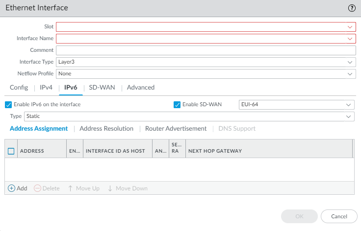
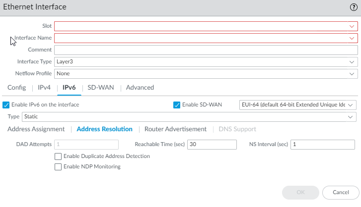
- (SD-WAN plugin 3.2.0 and later versions) To enable SD-WAN on an IPv6 interface, select the IPv6 tab, Enable IPv6 on the interface, and Enable SD-WAN.
- (SD-WAN plugin 3.2.0 and later versions) In the EUI-64 (default 64-bit Extended Unique Identifier) field, enter the 64-bit EUI in hexadecimal format. If you leave this field blank, the firewall uses the EUI-64 generated from the MAC address of the physical interface. If you enable the Use interface ID as host portion option when adding an address, the firewall uses the Interface ID as the host portion of that address.
- (SD-WAN plugin 3.2.0 and later versions) For an IPv6 interface, select the Type of address as Static. Select the Address Assignment tab.
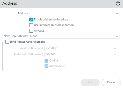
- Add an IPv6 Address for the interface or select New Variable to create the variable. SD-WAN supports one IPv6 address per physical interface.
- Enable address on interface.
- Use interface ID as host portion—See prior step for explanation.
- Anycast—Select to make the IPv6 address (route) an Anycast address (route), which means multiple locations can advertise the same prefix, and IPv6 sends the anycast traffic to the node it considers the nearest, based on routing protocol costs and other factors.
- Next Hop Gateway—Enter the IPv6 address of the Next Hop Gateway (the next hop from the IPv6 address you entered). The Next Hop Gateway must be on the same subnet as the IPv6 address. The Next Hop Gateway is the IP address of the ISP’s default router that the ISP gave you when you bought the service. It is the next hop IP address to which the firewall sends traffic to reach the ISP’s network, and ultimately, the internet and the hub.
- Send Router Advertisement—Select to enable the firewall to send this address in Router Advertisements (RAs), in which case you must also enable the global Enable Router Advertisement option for the interface (on the Router Advertisement tab).
- Valid Lifetime (sec)—Enter the valid lifetime (in seconds) that the firewall considers the address valid. The valid lifetime must equal or exceed the Preferred Lifetime (sec) (default is 2,592,000).
- Preferred Lifetime (sec)—Enter the preferred lifetime (in seconds) that the valid address is preferred, which means the firewall can use it to send and receive traffic. After the preferred lifetime expires, the firewall can't use the address to establish new connections, but any existing connections are valid until the valid lifetime expires (default is 604,800).
- On-link—Select if systems that have addresses within the prefix are reachable without a router.
- Autonomous—Select if systems can independently create an IP address by combining the advertised prefix with an Interface ID.
- Click OK.
- (SD-WAN plugin 3.2.0 and later versions) For a static IPv6 interface, configure address resolution.
- Select Address Resolution.
- Enable Duplicate Address Detection (DAD) if you want the uniqueness of a potential IPv6 address to be verified before it's assigned to the interface (default is enabled).
- If you selected Enable Duplicate Address Detection, specify the number of DAD Attempts within the neighbor solicitation (NS) interval before the attempt to identify neighbors fails; range is 1 to 10; default is 1.
- Enter the Reachable Time (sec), the length of time that the client assumes a neighbor is reachable after receiving a Reachability Confirmation message; range is 10 to 36,000; default is 30.
- Enter the NS Interval (sec) (Neighbor Solicitation interval), the length of time between Neighbor Solicitations; range is 1 to 3,600; default is 1
- Enable NDP Monitoring to enable Neighbor Discovery Protocol monitoring. When enabled, you can select the NDP icon in the Features column and view information such as the IPv6 address of a neighbor the firewall has discovered, the corresponding MAC address, User-ID, and status (on a best-case basis).
- Click OK.
- (SD-WAN plugin 3.2.0 and later versions) If you want to enable the interface to send IPv6 Router Advertisements (RAs) and optionally tune RA parameters, configure Router Advertisement as documented in the PAN-OS Networking Administrator's Guide, Configure Layer 3 Interfaces.
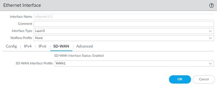
- On the SD-WAN tab, select an SD-WAN Interface Profile that you already created (or create a new SD-WAN interface profile) to apply to this interface. The SD-WAN Interface Profile has an associated link tag, so the interfaces where this profile is applied will have the associated link tag. An interface can have only one link tag.
- Click OK to save the Ethernet interface.
- Commit and Commit and Push your configuration changes.
- (SD-WAN manual configuration only) Configure a Virtual SD-WAN Interface. Auto VPN configuration will perform this task if you’re using Auto VPN.
Strata Cloud Manager
Configure Ethernet Layer 3 interfaces with SD-WAN functionality in Strata Cloud Manager.
Layer 3 interfaces are required for SD-WAN functionality. Repeat this
step to configure as many Layer 3 Ethernet interfaces on your SD-WAN
firewall as needed.
Configure a Layer 3 interface for your firewalls as part of the folder or snippet
configuration, or for a specific firewall.
- Log in to Strata Cloud Manager.
- Select and select the Configuration Scope where you want to create the Layer 3 interface.Select a firewall from your Folders or select Snippets to configure the Layer 3 interface in a snippet.If you select a folder or select a snippet, you create a Layer 3 interface variable that must be assigned at the device level.
- Add the interface.If you’re configuring a Layer 3 interface for a specific firewall, select the interface you want to configure instead.
- Folders and Snippets—Add Interface and select Interface.
- Firewalls—Add and Add Interface.
- Configure the interface.If you’re configuring an interface in the folder or snippet scope, the interface configuration is pushed only to firewalls that have the corresponding interface slot available. For example, if you configure Ethernet 1/5 in the folder scope and the firewall associated with the folder has only four interface slots, then the configuration isn’t pushed to the firewall.
- Select the interface Slot.
- Select the Interface Name.When you configure an interface for a specific firewall, the Interface Name is fixed, such as ethernet1/1 if you select Slot 1. The fixed interface names are dependent on the slot that you selected in the previous step.
- (Folders and Snippets only) Select the Default Interface Assignment.
- (Optional) Enter a Description.
- For Interface Type, select Layer3.
- (Folders and Snippets only; Optional) Assign the interface to a Logical Router.See configure a logical router for more information.
- (Folders and Snippets only; Recommended) Assign the interface to a Zone.Create New to create a new zone. See zone protection and DoS protection for more information.
- Configure interface IP settings.
- Select the interface IP Type.
- Static IPv4 Address.Add the IPv4 IP addresses for the interface.You can configure up to four IP addresses when you're configuring a Layer 3 Ethernet interface for the SD-WAN functionality. Whereas the Auto VPN workflows uses only the first IP address from the configured IPv4 address list to create the VPN tunnel.
- Activate the DHCP Client on the interface.See configure an interface as a DHCP client for more information on configuring the interface as a DHCP client.
- Activate PPPoE and configure the connection settings.Enable to activate the interface for Point-to-Point Protocol over Ethernet (PPPoE) termination. This makes the interface a PPPoE termination point to support connectivity in a Digital Subscriber Line (DSL) environment where there’s a DSL modem but no other PPPoE device to terminate the connection.
- (Optional) Configure the interface link settings.
- Expand the Advanced Settings.
- Select the interface Link Speed.Auto is selected by default and allows the firewall to determine the speed.
- Select the interface Link Duplex transmission mode.Auto is selected by default to allow the firewall to negotiate the transmission mode automatically.
- Select the interface Link State.Auto detect is selected by default to allow the firewall to determine the link state.
- Assign the interfaces to the aggregate interface group.
- Select and select the appropriate Configuration Scope.You can select a folder or firewall from the Config Tree or select Snippets to configure the interface in a snippet.
- Save.
- Push Config to push your configuration changes.