Simplified Onboarding of VM-Series Firewall on Azure
Table of Contents
Simplified Onboarding of VM-Series Firewall on Azure
Simplified onboarding of VM-Series on Azure.
The simplified onboarding flow streamlines the deployment and initial
configuration of VM-Series firewalls in Azure. This flow deploys production-ready
out-of-the-box architecture and firewall configuration for users who may be new to
VM-Series on Azure.
The firewall configuration includes essentials like interfaces (ethernet1/1 and
ethernet1/2), zones (untrust and trust), virtual Routers (untrust-vr and trust-vr),
static routes, outbound NAT policies, and security policies (defaults to allow health
probe traffic).
Prerequisites
For simplified onboarding of VM-Series firewall on Azure, ensure to use the
following PAN-OS versions and license types:
Supported PAN-OS Version
- PAN-OS version 10.2.14 or above
- PAN-OS version 11.1.8 or above
- PAN-OS version 11.2.5 or above
Supported License Types
- BYOL (Bring your own license)
- PAYG (Pay-as-you-go)
Simplified Onboarding for VM Series Solution templates on Azure Marketplace
Azure Marketplace Solution Templates support both Single Firewall and load
balancer based reference architectures.
The following are the steps for a simplified onboarding of multiple
VM-Series firewalls with load balancers.
- Navigate to Azure Marketplace.
- Log in to the Azure portal.
- In the Azure portal dashboard, click the search bar at the top.
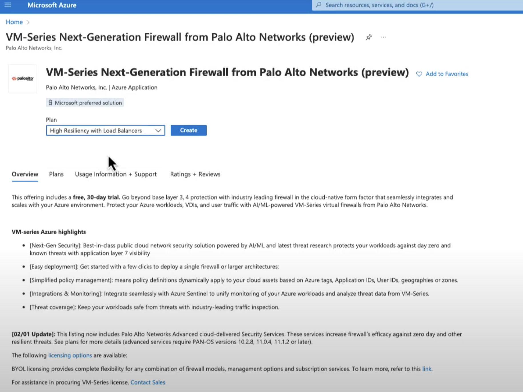
- Search for VM-Series Next-Generation Firewall and select the listing titled VM-Series Next-Generation Firewall by Palo Alto Networks.
![]()
- In the Plan drop down menu, select High Resiliency with Load Balancers.
- Click Create on the marketplace overview page.
- Basic configuration.Configure basic settings for the firewall.
- Select your Azure Subscription.
- Create a new resource group or select an existing resource group that is empty. The resource group will hold all the resources associated with the VM-Series firewall for this deployment.
- Azure has removed the option to select an existing resource group for Marketplace solutions that enable multiple network interface controllers (NICs). To deploy the firewall into an existing resource group, use the ARM template in the GitHub Repository or use your own custom ARM template.
- Select the Azure Region in which you are deploying the firewall.
- Enter a Username for the firewall administrator.
- Select the Authentication type—Password or SSH Public Key.
- Enter a Password (up to 31 characters) or copy and paste an SSH public key for securing administrative access to the firewall.
- Confirm the password.
- Select the License Type.
- Enter the Deployment Tag that you specified while creating the resource group.
- Click Next.
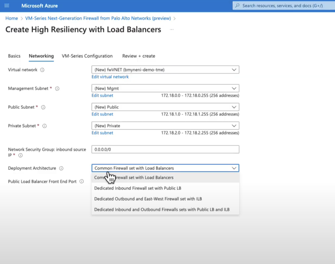
- Configure networking.You can see that the Virtual Network, management subnet, public subnet, private subnet, and Network Security group IP addresses are already populated.
- Select the Deployment architecture.
![]() VM-Series with high resiliency load balancers support four different deployment architectures: Common firewall set with LB, Dedicated inbound firewall set with Public LB, Dedicated outbound and east-west firewall set with ILB, and Dedicated inbound and outbound firewalls sets with public LB and ILB. Select one of these for your deployment architecture. For more information, see Deploy the VM-Series Firewall from the Azure Marketplace (Solution Template).
VM-Series with high resiliency load balancers support four different deployment architectures: Common firewall set with LB, Dedicated inbound firewall set with Public LB, Dedicated outbound and east-west firewall set with ILB, and Dedicated inbound and outbound firewalls sets with public LB and ILB. Select one of these for your deployment architecture. For more information, see Deploy the VM-Series Firewall from the Azure Marketplace (Solution Template). - Click Next.
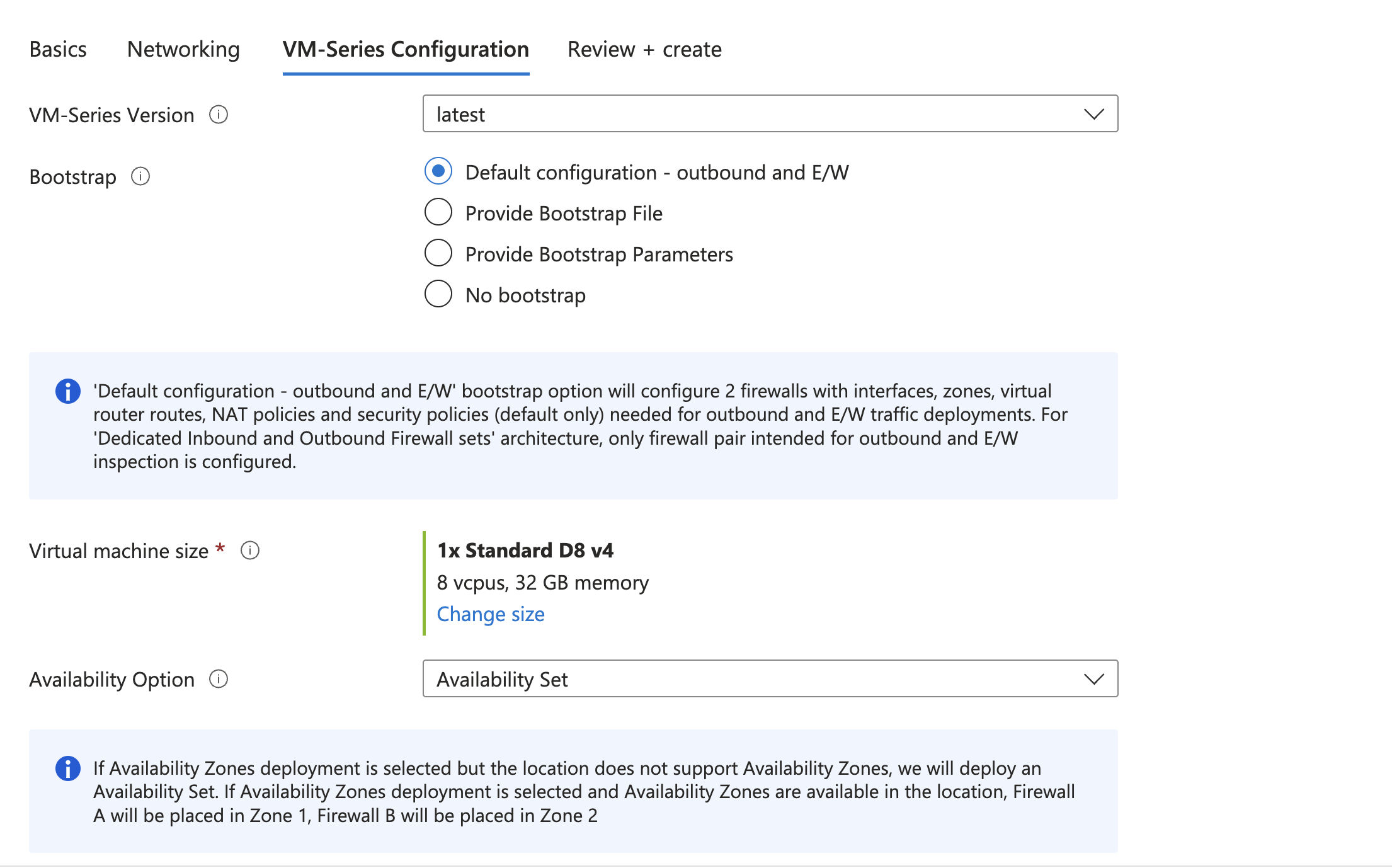
- VM-Series Configuration.
- Select the VM-Series Version.
- Select the Default configuration - outbound and E/W bootstrap option to boot the firewalls with default pre-configurations needed for outbound traffic inspection.
![]()
- Select the Availability Option
- Click Next.
- Review the summary, and OK. Then accept the terms of use and privacy policy, and click Create to launch the firewall.
- OptionalValidate Firewall Configuration
- Log in to the VM-Series firewall web interface. For more information, see Launch the firewall web interface.
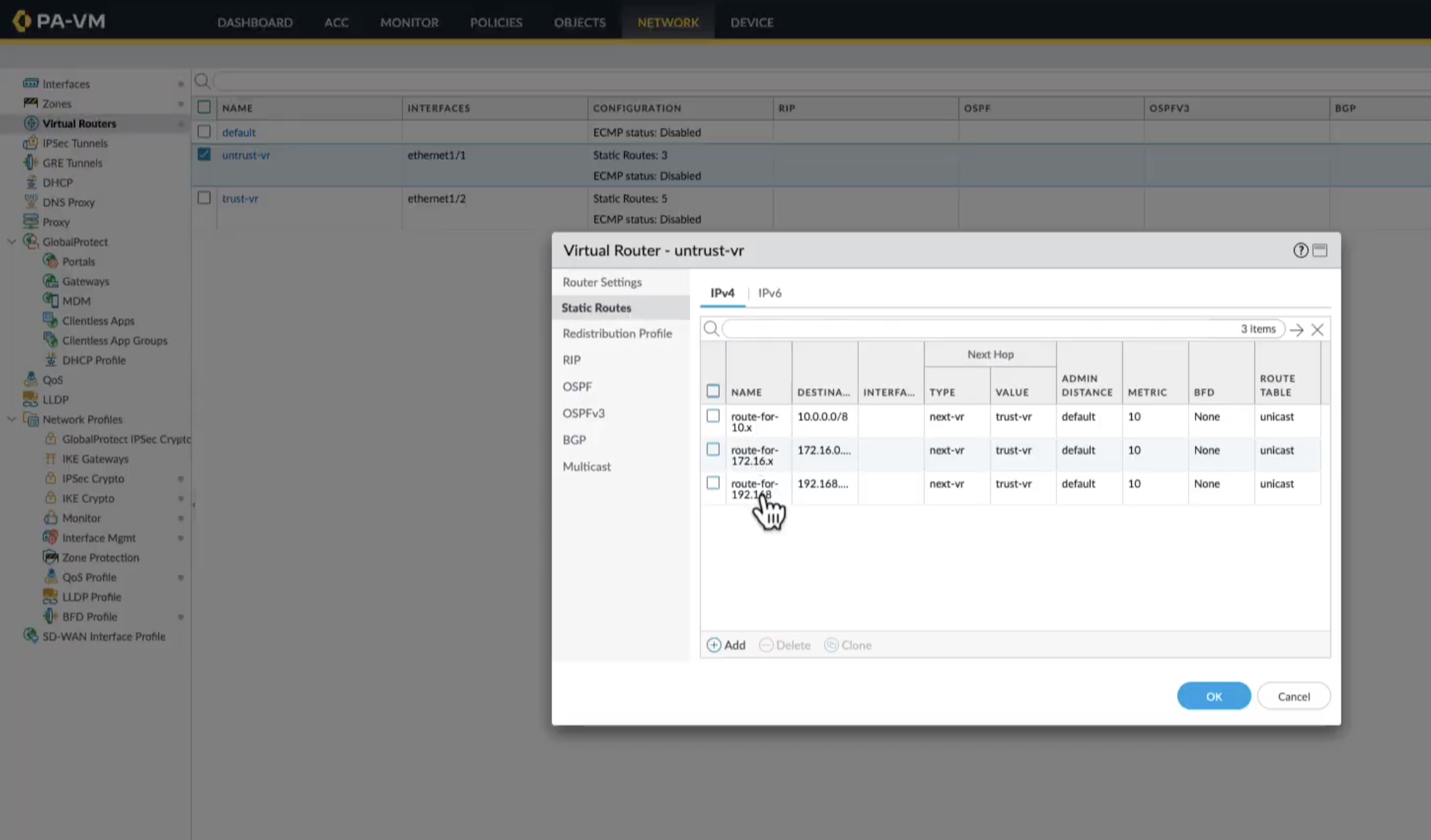
- Go to the Network tab.
- Click interfaces and verify if the interfaces are correctly assigned:
- Ethernet1/1 should be in the Untrust zone.
- Ethernet1/2 should be in the Trust zone.
- Verify Routing. In the Virtual Router section, ensure static routes for outbound and east-west traffic are present.
![]()
- Verify Security Policies.Navigate to the Policies tab and confirm default rules are present:
- Intra-zone traffic is allowed.
- Inter-zone traffic is denied.
Verify the presence of a NAT policy for outbound internet traffic.
- Peer Application VNet with the trust Vnet
- Navigate to the Azure portal and open the FirewallVNet resource.
- Go to the Peerings section.
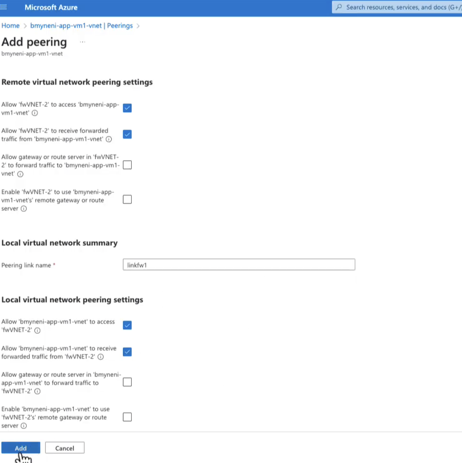
![]()
- Click Add.
- Enter a name.
- Select the application VNet whose traffic you wish to inspect
- Click Add to create the peering.
You can repeat the above process to peer the FirewallVNet with AppVNet2. - Configure Route Tables for each application subnet.
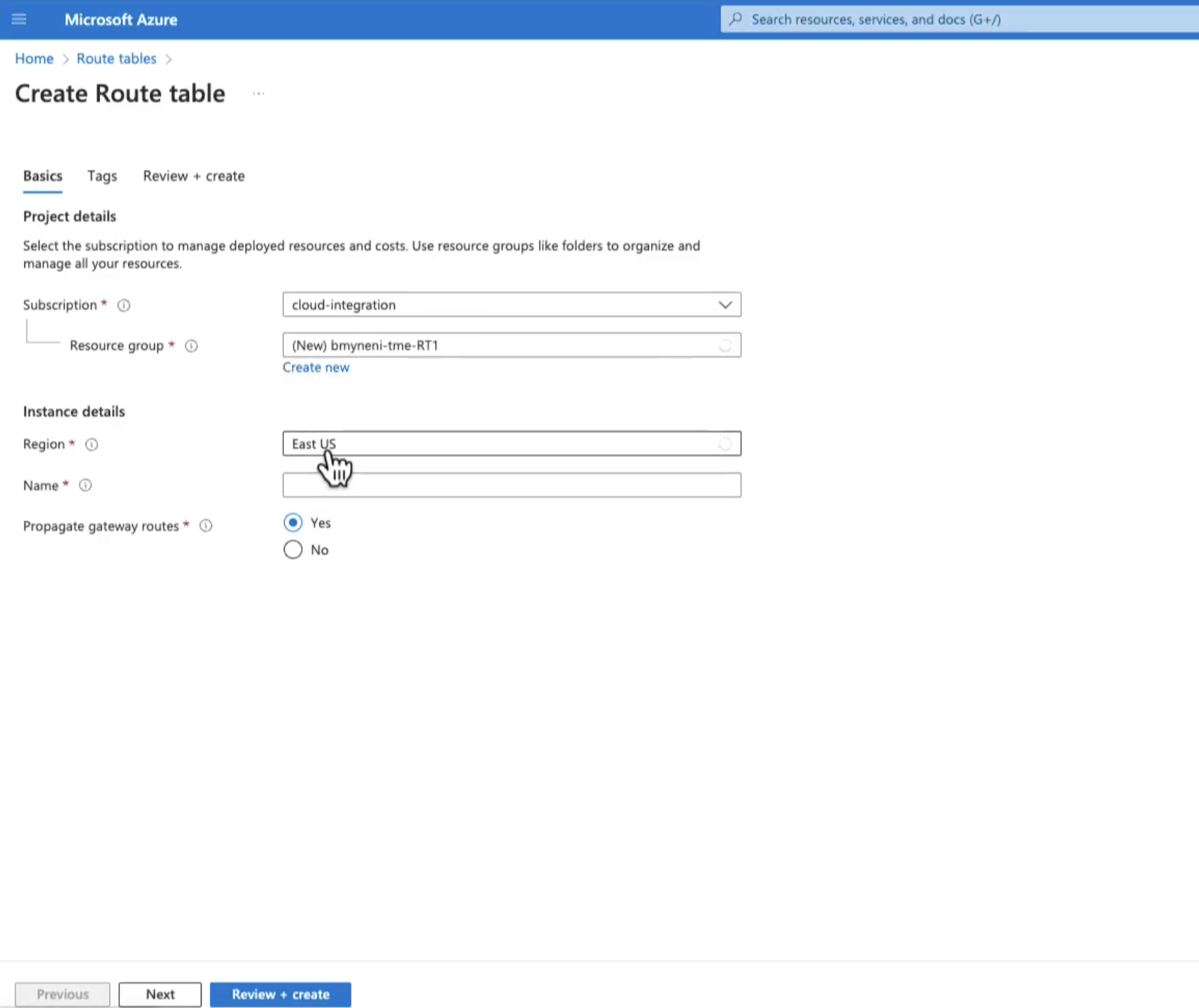
![]()
- Create Route tables for each application subnet:
- Go to Route Tables in the Azure portal and click Create.
- Enter the Region and Name the table (e.g., AppVM1RouteTable) and associate it with the subnet of AppVNet1.
- Repeat the process for AppVNet2.
- Add Routes:You must add two routes to each table:Route 1- Outbound Traffic:
- Enter the Destination IP address.
- Enter the Next Hop type.
- Enter the Next Hop IP Address. This should be the frontend IP of the firewall’s load balancer.
- Click Add.
Route 2 - East-West Traffic:- Enter the Destination IP address. This is the subnet of the other application VNet.
- Enter the Next Hop type.
- Enter the Next Hop IP Address. This should be the frontend IP of the firewall’s load balancer.
You must add two routes to each table:Route 1- Outbound Traffic:- Enter the Destination IP address.
- Enter the Next Hop type.
- Enter the Next Hop IP Address. This should be the frontend IP of the firewall’s load balancer.
- Click Add.
Route 2 - East-West Traffic:- Enter the Destination IP address. This is the subnet of the other application VNet.
- Enter the Next Hop type.
- Enter the Next Hop IP Address. This should be the frontend IP of the firewall’s load balancer.
- Click Add.