PAN-1RU-4POST-RACK-11
Table of Contents

PAN-1RU-4POST-RACK-11
Install a PA-520, PA-540, PA-550, or PA-560 firewall in an equipment rack using the
PAN-1RU-4POST-RACK-11 mounting kit.
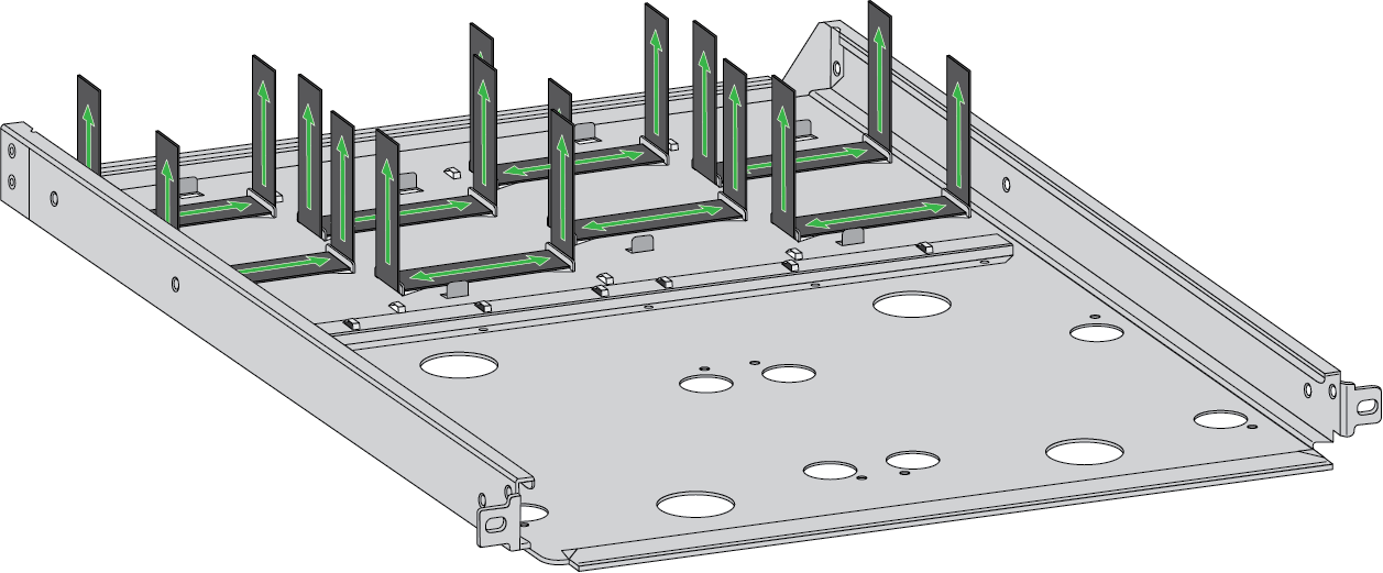
- Secure the power adapter(s) to the mounting tray.
- For each power adapter being installed (for a maximum of four for the
PA-520 and PA-540 and a maximum of two for the PA-550 and PA-560), feed
two Velcro straps through the openings at the dedicated power adapter
locations on the mounting tray.
![]()
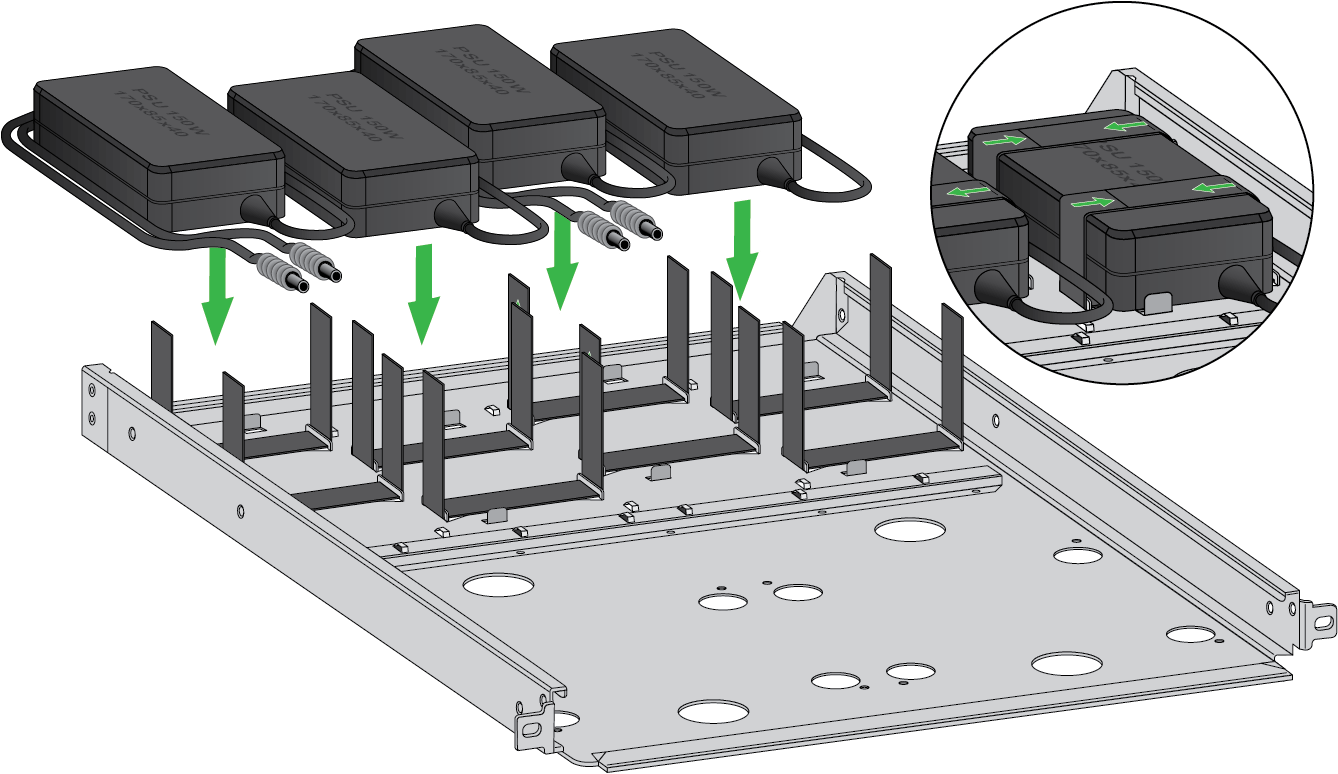
- Place each power adapter into its designated location, then wrap both
Velcro straps over the top of the adapter so that the adapter is fixed
in place.
![]()
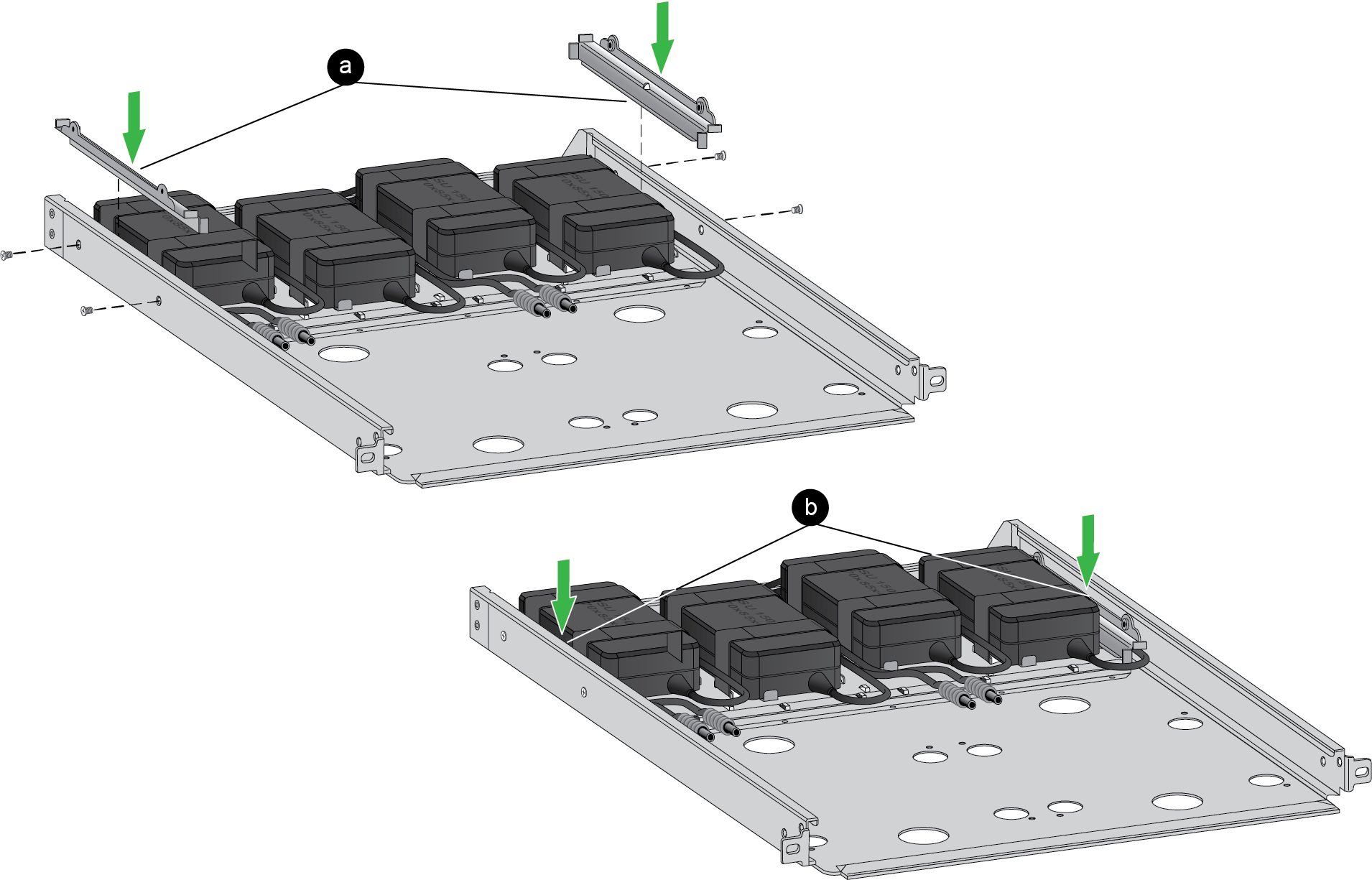
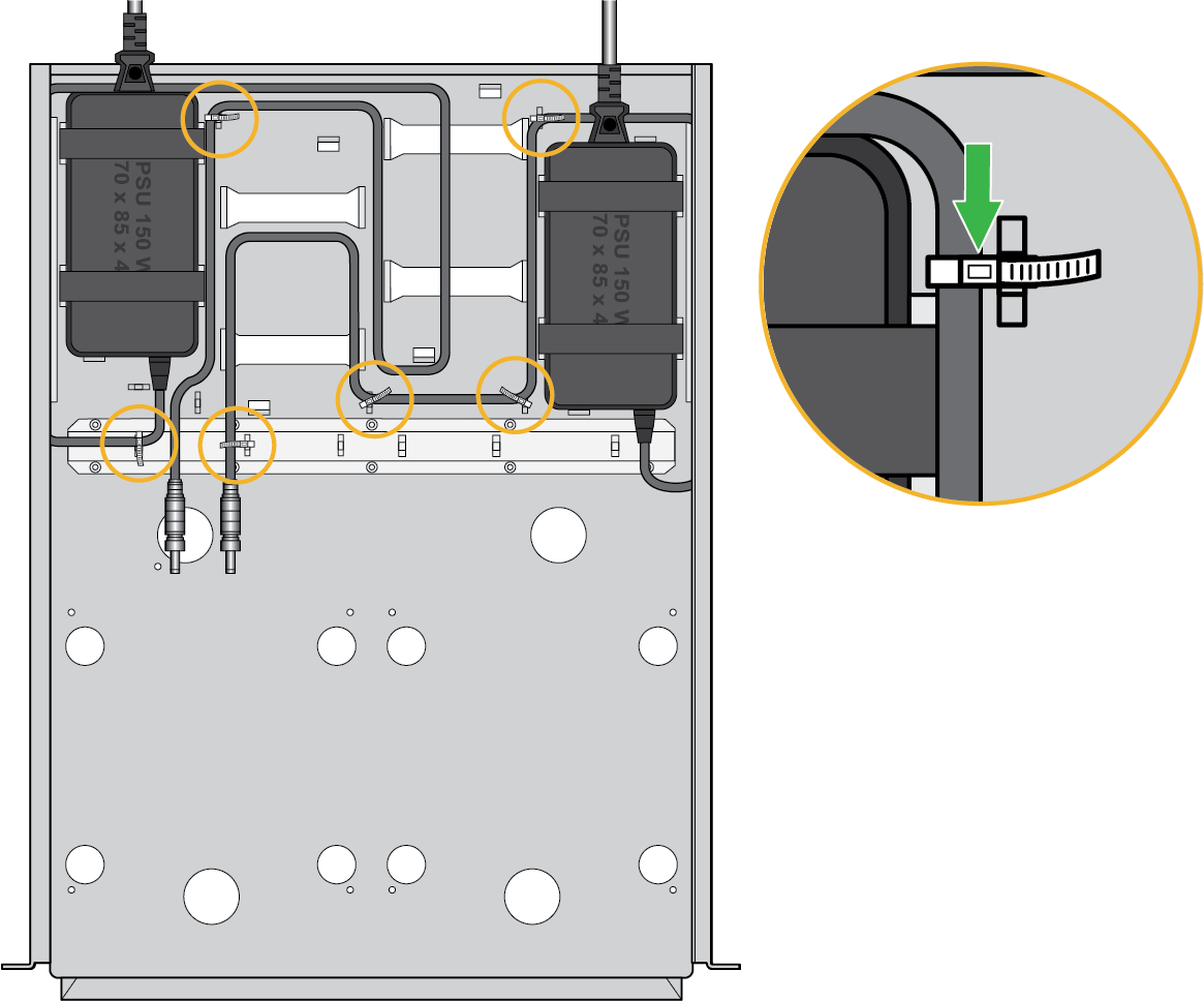
Route the power cables through paths on the mounting tray.- Route the initial segment of the power cables (that plugs into the
firewall) along the wall of the mounting tray. Use two #6-32 screws to
install a routing cover over each wall of the mounting tray so that the
power cable is contained within.
![]()
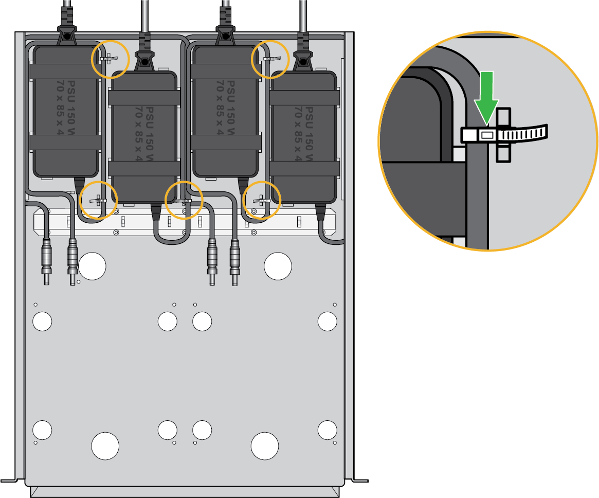
- Using the following images as references, guide the remaining length of
the power cables along the mounting tray. Thread the provided cable ties
through the lances and cutouts in the mounting tray. Wrap the cable ties
around the power cables, ensuring that the power cables are fixed in
place.PA-520 and PA-540
![]() PA-550 and PA-560
PA-550 and PA-560![]()
Install retention clamps over the power cord that plugs into your power source.- Connect the power cords into each power adapter.
- Thread each power cord through a retention clamp, then snap the
retention clamp to the mounting tray.
![]()
- Tighten the retention clamp so that the power cord is locked in
place.
![]()
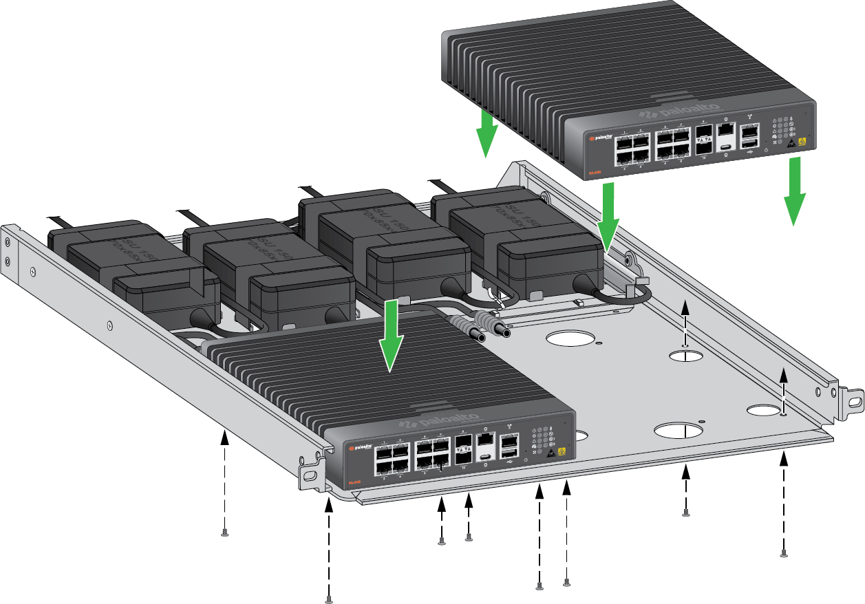
Install the firewall in the mounting tray.PA-520 and PA-540- Align the four rubber feet of each device to the mounting tray, then
secure it using four M3 x 6mm flathead screws. Repeat if you are
installing a second firewall.
![]()
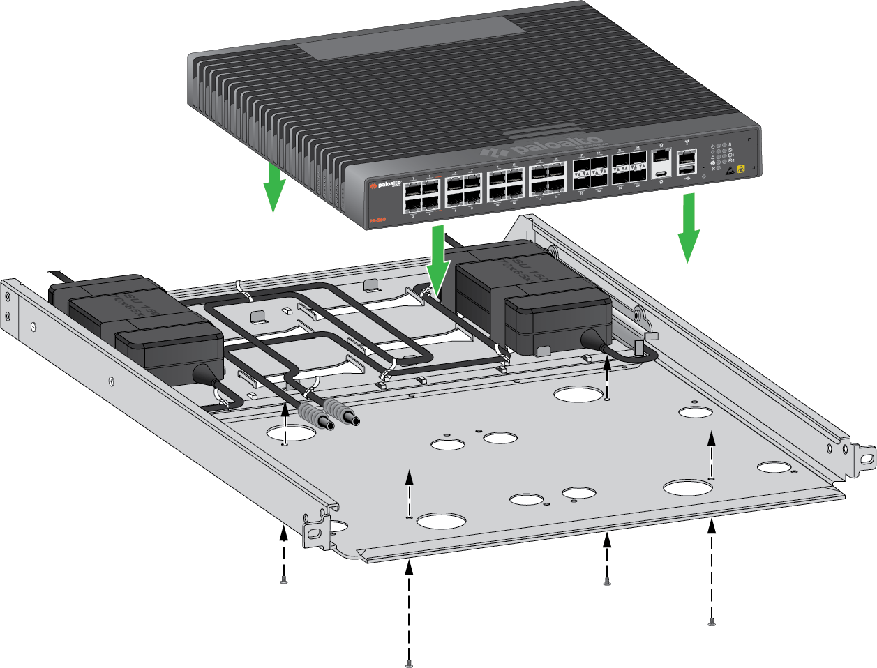
PA-550 and PA-560- Align the four rubber feet of the device to the mounting tray, then
secure it using four M3 x 6mm flathead screws.
![]()
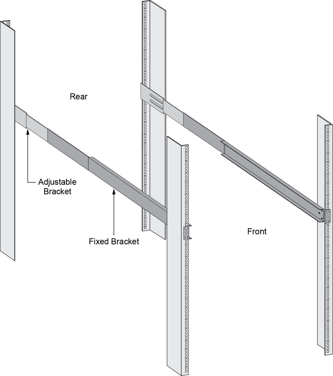
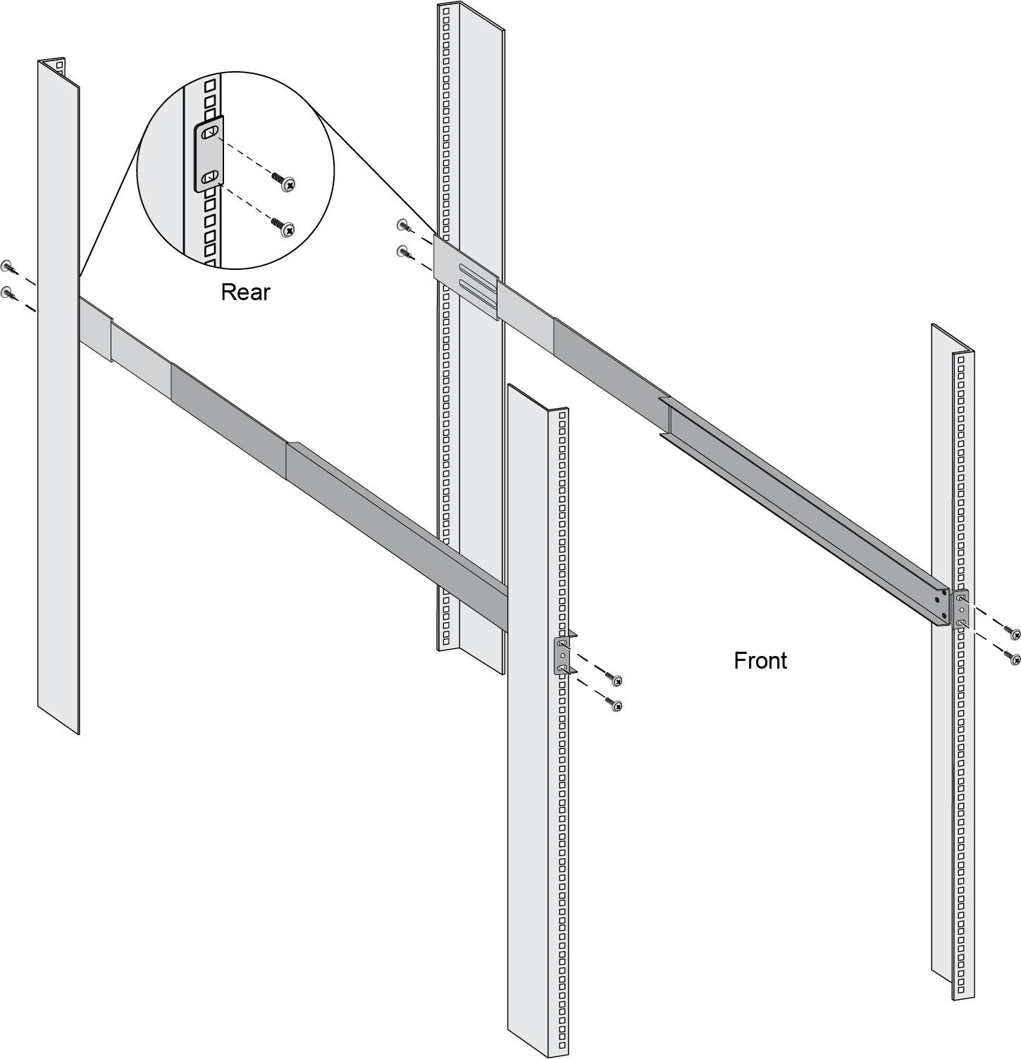
Slide one of the adjustable mounting brackets into one of the fixed mounting brackets to create a mounting rail. Repeat for the second mounting rail. The adjustable and fixed brackets are the same for the left and right side.![]() Align the bottom edge of the mounting rails to the bottom of the space reserved for your firewall. Align the slotted holes in the adjustable mounting bracket to the holes on the rear of the equipment frame.Secure the rails to the equipment frame with mounting screws (not provided) compatible with your equipment frame. Tighten the screws to their recommended torque value.
Align the bottom edge of the mounting rails to the bottom of the space reserved for your firewall. Align the slotted holes in the adjustable mounting bracket to the holes on the rear of the equipment frame.Secure the rails to the equipment frame with mounting screws (not provided) compatible with your equipment frame. Tighten the screws to their recommended torque value.![]() Slide the mounting tray into the rails previously fixed to the equipment rack. Stop when the front flange on the mounting tray is flush with the front of the rail.Align the slotted hole in the mounting tray to the hole in the equipment frame. Secure the mounting tray to the equipment frame on both sides using one screw each (not provided). The screws must be compatible with your equipment frame.
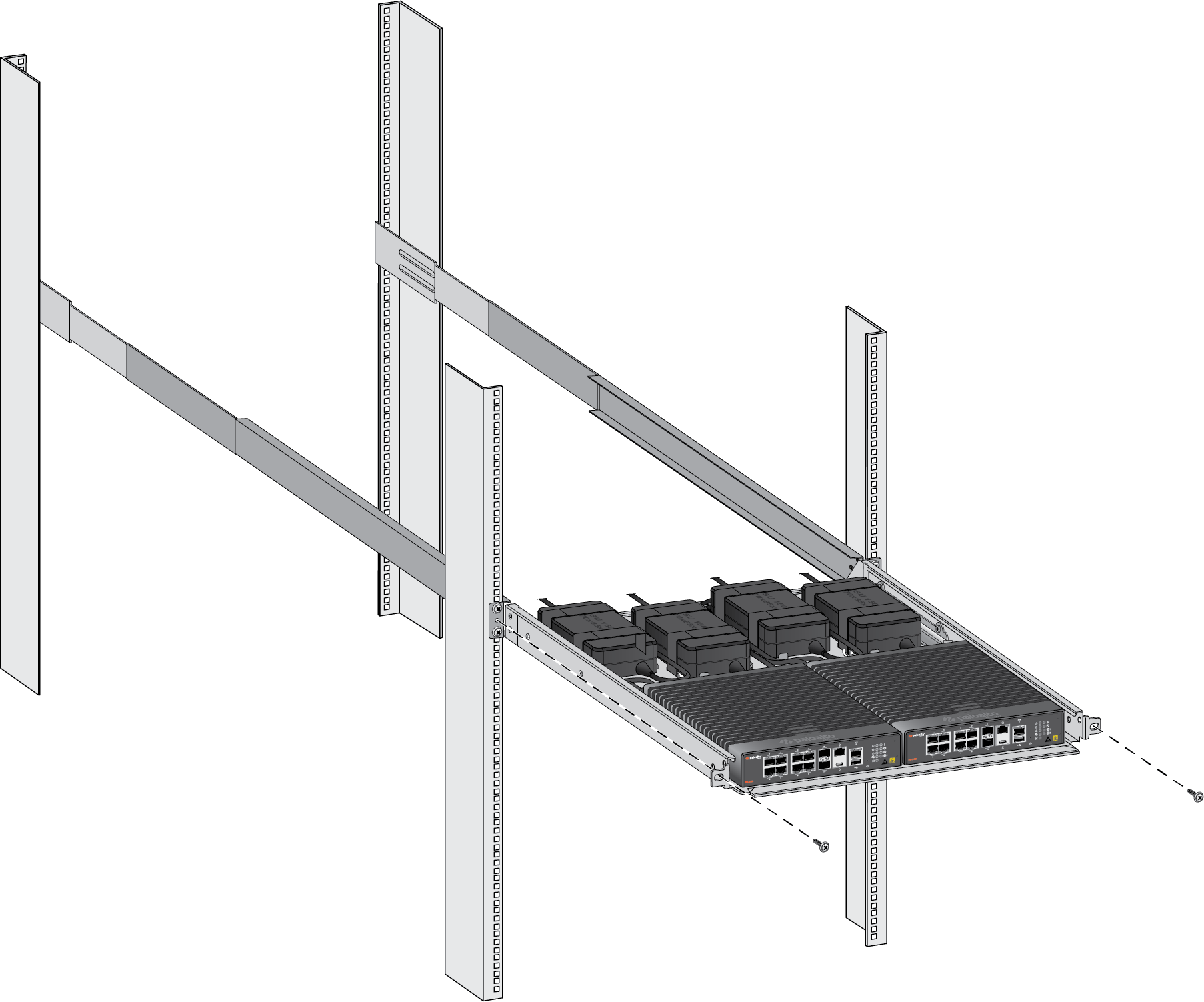
Slide the mounting tray into the rails previously fixed to the equipment rack. Stop when the front flange on the mounting tray is flush with the front of the rail.Align the slotted hole in the mounting tray to the hole in the equipment frame. Secure the mounting tray to the equipment frame on both sides using one screw each (not provided). The screws must be compatible with your equipment frame.![]() Proceed to Connect Power to the PA-500 Series Firewall.
Proceed to Connect Power to the PA-500 Series Firewall.
- For each power adapter being installed (for a maximum of four for the
PA-520 and PA-540 and a maximum of two for the PA-550 and PA-560), feed
two Velcro straps through the openings at the dedicated power adapter
locations on the mounting tray.