
PA-500 Series Firewall Components
Table of Contents

PA-500 Series Firewall Components
View the components and descriptions of the PA-500 Series firewall.
Refer to the following sections to view the front and back panel components of the
PA-500 Series firewalls.
To review the specifications of supported Palo Alto Networks®
interfaces and transceivers, refer to the datasheet.
PA-501 and PA-505
View the front and back panel components of the PA-501 and PA-505
firewalls.
The following image shows the front panel
of the PA-501 and PA-505, which have the
same front panel components (PA-505 pictured). The table describes
each front panel component.
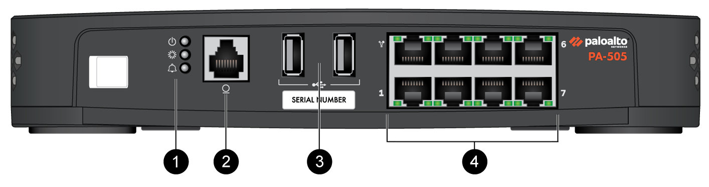
| Item | Component | Description |
|---|---|---|
|
1
|
LED Status Indicators
|
Three LEDs that indicate the status of the firewall hardware
components (see PA-500 Series Firewall LED Definitions).
|
|
2
|
Console Port
|
Use this port to connect a management computer to the firewall using
a 9-pin serial to RJ-45 cable and terminal emulation software.
The console connection provides access to firewall boot messages, the
Maintenance Recovery Tool (MRT), and the command line interface
(CLI).
If your management computer does not have a serial port, use a
USB-to-serial converter. Use the following settings to configure your terminal emulation
software to connect to the console port:
|
|
3
|
USB Ports
|
Two USB ports for debugging and administration only. Use one of the
two ports to bootstrap the firewall.
Bootstrapping enables you to provision the firewall with a specific
PAN-OS configuration and then license it and make it operational on
your network.
In PAN-OS 12.2.2 and later versions, you can use this USB port
to perform self-service enhanced factory reset (EFR). EFR
provides remediation of a compromised or potentially compromised
firewall to initiate a complete cleanup of the device. |
|
4
|
RJ-45 Ports
|
Management Port
One Ethernet10/100/1000Mbps port (the top-left port) that is used to
access the management web interface and perform administrative
tasks. The firewall also uses this port for management services,
such as retrieving licenses and updating threat and application
signatures.
Ethernet Ports
Seven RJ-4510/100/1000Mbps ports for network traffic.You can set the
link speed and duplex mode or choose autonegotiate.
|
The following image shows the back panel of the PA-501 and PA-505, which have the same
back panel components (PA-505 pictured). The table describes each back
panel component.
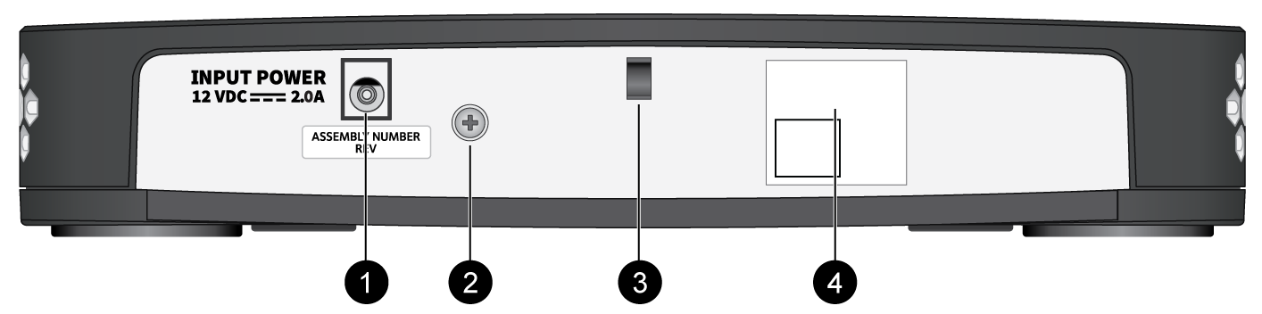
| Item | Component | Description |
|---|---|---|
|
1
|
Power Adapter Input
|
Use the power input to connect power to the firewall. The PA-505
ships with one 25W power adapter.
|
|
2
|
Ground Stud
|
Use the single post ground stud to connect the firewall to earth
ground (ground cable not included).
|
|
3
|
Power Cord Retainer
|
Use the power cord retainer to secure the power cord.
|
|
4
|
QR Code
|
Scan the QR code to access product and ZTP onboarding
information.
|
PA-510
View the front and back panel components of the PA-510 firewall.
The
following image shows the front panel of the PA-510. The table describes each front
panel component.
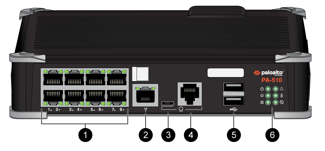
| Item | Component | Description |
|---|---|---|
|
1
|
Ethernet ports
|
Eight RJ-45 10/100/1000Mbps ports for network traffic.
You can set the link speed and duplex mode or choose
auto-negotiate.
|
|
2
|
Management port
|
Use this Ethernet 1Gbps port to access the management web interface
and perform administrative tasks. The firewall also uses this port
for management services, such as retrieving licenses and updating
threat and application signatures.
|
|
3
|
CONSOLE port
(Micro USB)
|
Use this port to connect a management computer to the firewall using
a standard Type-A USB-to-micro USB cable.
The console connection provides access to firewall boot messages, the
Maintenance Recovery Tool (MRT), and the command line interface
(CLI).
Refer to Micro USB Console Port for
more information and to download the Windows driver or to learn how
to connect from a Mac or Linux computer.
|
|
4
|
CONSOLE port
(RJ-45)
|
Use this port to connect a management computer to the firewall using
a 9-pin serial to RJ-45 cable and terminal emulation software.
The console connection provides access to firewall boot messages, the
Maintenance Recovery Tool (MRT), and the command line interface
(CLI).
If your management computer does not have a serial port, use a
USB-to-serial converter. Use the following settings to configure your terminal emulation
software to connect to the console port:
|
|
5
|
USB ports
|
Two USB ports for debugging and administration only. Use one of these
ports to bootstrap the firewall.
Bootstrapping enables you to provision the firewall with a specific
PAN-OS configuration and then license it and make it operational on
your network.
In PAN-OS 12.2.2 and later versions, you can use this USB port
to perform self-service enhanced factory reset (EFR). EFR
provides remediation of a compromised or potentially compromised
firewall to initiate a complete cleanup of the device. |
|
6
|
LED status indicators
|
Six LEDs that indicate the status of the firewall hardware components
(see PA-500 Series Firewall LED Definitions).
|
The following image
shows the back panel of the PA-510. The table describes each back panel component.
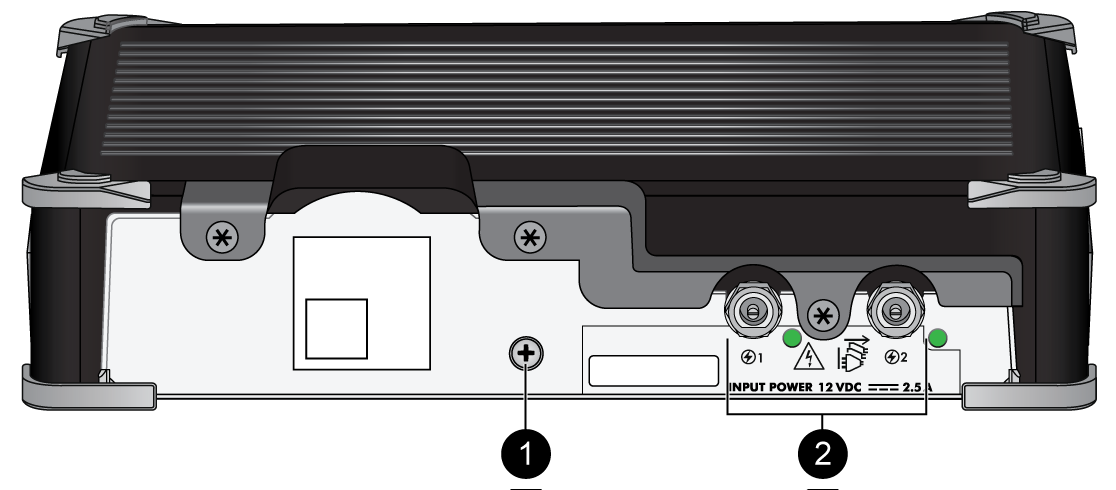
| Item | Component | Description |
|---|---|---|
|
1
|
Ground stud
|
Use the single post ground stud to connect the firewall to earth
ground (ground cable not included).
|
|
2
|
Power adapter inputs
|
Use the power inputs to connect power to the firewall. A second
adapter can be used for redundancy.
|
PA-520 and PA-540
View the front and back panel components of the PA-520 and PA-540
firewalls.
The following image shows the front panel
of the PA-520 and PA-540, which have similar front panel components (PA-540
pictured). The main difference is that the PA-520 does not have SFP ports. The
table describes each front panel component.
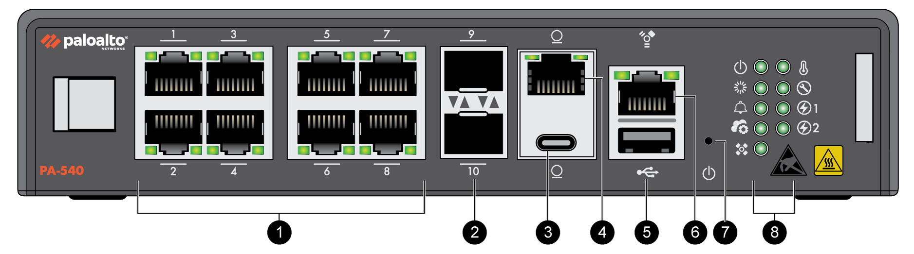
| Item | Component | Description |
|---|---|---|
|
1
|
RJ-45 Ports
|
Eight copper RJ-45 10Mbps/100Mbps/1Gbps ports for network
traffic.
Port 1 is a Zero Touch Provisioning (ZTP)
port. The ZTP port can be used to automatically provision the
firewall. |
|
(PA-540 only)
2
|
SFP Ports
|
Two SFP 1Gbps ports for network traffic.
|
|
3
|
Console port
(USB-C)
|
Use this port to connect a management computer to the firewall using
a standard USB-C cable.
The console connection provides access to firewall boot messages, the
Maintenance Recovery Tool (MRT), and the command line interface
(CLI).
|
|
4
|
Console port
(RJ-45)
|
Use this port to connect a management computer to the firewall using
a RJ-45 to USB cable and terminal emulation software.
The console connection provides access to firewall boot messages, the
Maintenance Recovery Tool (MRT), and the command line interface
(CLI).
Use the following settings to configure your terminal emulation
software to connect to the console port:
|
|
5
|
USB Port
|
One USB port for debugging and administration only. Use the port to
bootstrap the firewall.
Bootstrapping enables you to provision the firewall with a specific
PAN-OS configuration and then license it and make it operational on
your network.
In PAN-OS 12.2.2 and later versions, you can use this USB port
to perform self-service enhanced factory reset (EFR). EFR
provides remediation of a compromised or potentially compromised
firewall to initiate a complete cleanup of the device. |
|
6
|
Management Port
|
Use this RJ-45 1Gbps port to access the management web interface and
perform administrative tasks. The firewall also uses this port for
management services, such as retrieving licenses and updating threat
and application signatures.
|
|
7
|
Reset Button
|
A pin press reset button that can be used to gracefully shut down the
firewall.
|
|
8
|
LED Status Indicators
|
Nine LEDs that indicate the status of the firewall hardware
components (see PA-500 Series Firewall LED Definitions).
|
The following image shows the back panel of the
PA-520 and PA-540, which have similar back panel components (PA-540
pictured). The table describes each back panel component.
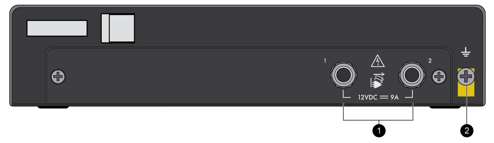
| Item | Component | Description |
|---|---|---|
|
1
|
Power Adapter Inputs
|
Two DC power inputs. One power supply is required, while a second
power supply can be used for redundancy.
|
|
2
|
Ground Stud
|
Use the single post ground stud to connect the firewall to earth
ground (ground cable not included).
|
PA-520-5G
View the front and back panel components of the PA-520-5G firewall.
The following image shows the front panel of the
PA-520-5G. The table describes each front panel component.
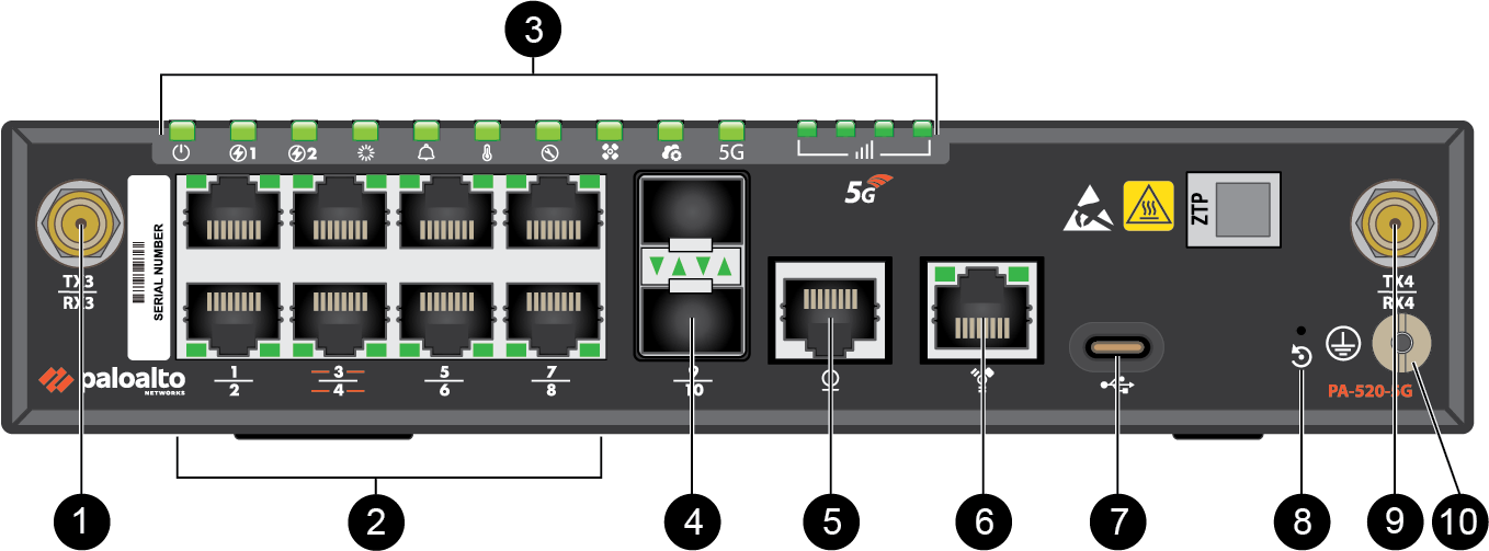
| Item | Component | Description |
|---|---|---|
|
1
|
5G Antenna Connector (TX3/RX3)
|
SMA antenna connector for connecting an external 5G antenna to the
firewall.
The 5G antennas also support GPS and
GLONASS (GNSS) for location services. No separate GPS antenna is
required. |
|
2
|
RJ-45 Ports
|
Eight copper RJ-45 10Mbps/100Mbps/1Gbps ports for network
traffic.
Port 1 is a Zero Touch Provisioning (ZTP)
port. The ZTP port can be used to automatically provision the
firewall. ZTP is also supported on Cellular 1/1;
whichever interface establishes connectivity first is used for
bootstrapping. Ports 3 and 4 are fail-open ports. They can be configured to
provide a pass-through connection despite power or operating
system failure. |
|
3
|
LED Status Indicators
|
Ten LEDs that indicate the status of the firewall hardware components
and four LEDs that indicate cellular connection strength. (see PA-500 Series Firewall LED Definitions).
|
|
4
|
SFP Ports
|
Two SFP 1Gbps ports for network traffic.
|
|
5
|
Console port
(RJ-45)
|
Use this port to connect a management computer to the firewall using
a RJ-45 to USB cable and terminal emulation software.
The console connection provides access to firewall boot messages, the
Maintenance Recovery Tool (MRT), and the command line interface
(CLI).
Use the following settings to configure your terminal emulation
software to connect to the console port:
|
|
6
|
Management Port
|
Use this RJ-45 10/100/1000 Mbps port to access the management web
interface and perform administrative tasks. The firewall also uses
this port for management services, such as retrieving licenses and
updating threat and application signatures.
|
|
7
|
USB Port
|
One USB-C port used for debugging and administration only. Use it to
bootstrap the firewall or perform self-service enhanced factory
reset (EFR).
Bootstrapping enables you to provision the firewall with a specific
PAN-OS configuration and then license it and make it operational on
your network.
EFR provides remediation of a compromised or potentially compromised
firewall to initiate a complete cleanup of the device.
In PAN-OS 12.2.2 and later versions, you can use this USB port to perform self-service enhanced factory reset (EFR). EFR provides remediation of a compromised or potentially compromised firewall to initiate a complete cleanup of the device. |
|
8
|
Reset Button
|
A pin press reset button that can be used to gracefully shut down the
firewall.
|
|
9
|
5G Antenna Connector (TX4/RX4)
|
SMA antenna connector for connecting an external 5G antenna to the
firewall.
|
|
10
|
Ground Stud
|
Use the single post ground stud to connect the firewall to earth
ground (ground cable not included).
|
The following image shows the back panel of the
PA-520-5G. The table describes each back panel component.
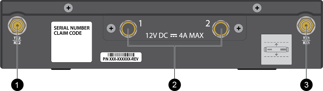
| Item | Component | Description |
|---|---|---|
|
1
|
5G Antenna Connector (TX2/RX2)
|
SMA antenna connector for connecting an external 5G antenna to the
firewall.
|
|
2
|
Power Adapter Inputs
|
Two DC 12V power inputs (PS1 and PS2). One power supply is
required; a second can be used for redundancy. The two inputs do not
support load sharing.
|
|
3
|
5G Antenna Connector (TX1/RX1)
|
SMA antenna connector for connecting an external 5G antenna to the
firewall.
|
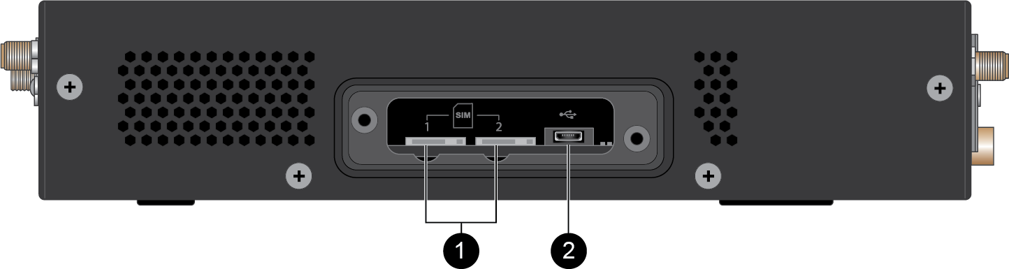
The following image shows the side panel of the PA-520-5G after the SIM
cover has been removed. The table describes each side panel component.
| Item | Component | Description |
|---|---|---|
|
1
|
SIM Slots
|
Two nano SIM card slots (SIM 1 and SIM 2). The firewall supports
Active/Standby SIM selection. The firewall also supports an embedded
SIM (eUICC).
|
|
2
|
Micro USB-C Port
|
This port is reserved for internal use and is not available for
configuration.
|
PA-550 and PA-560
View the front and back panel components of the PA-550 and PA-560
firewalls.
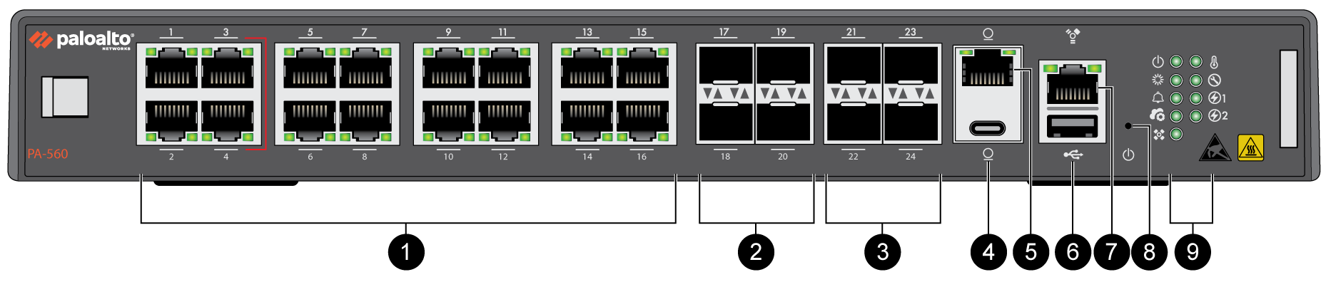
The following image shows the front panel
of the PA-550 and PA-560, which have similar front panel components (PA-560
pictured). The table describes each front panel component.
| Item | Component | Description |
|---|---|---|
|
1
|
RJ-45 Ports
|
PA-550
Twelve copper RJ-45 10Mbps/100Mbps/1Gbps ports for network
traffic.
PA-560
Sixteen copper RJ-45 10Mbps/100Mbps/1Gbps ports for network
traffic.
Port 1 is a Zero Touch Provisioning (ZTP)
port. The ZTP port can be used to automatically provision the
firewall. Ports 3 and 4 are fail-open ports. They can be configured to
provide a pass-through connection despite power or operating
system failure. |
|
2
|
SFP Ports
|
PA-550
Two SFP 1Gbps ports for network traffic. (Ports 13 and 14)
PA-560
Four SFP 1Gbps ports for network traffic. (Ports 17 through 20)
|
|
3
|
SFP/SFP+ Ports
|
PA-550
Two SFP/SFP+ 1Gbps/10Gbps ports for network traffic. (Ports 15 and
16)
PA-560
Four SFP/SFP+ 1Gbps/10Gbps ports for network traffic. (Ports 21
through 24)
|
|
4
|
Console port
(USB-C)
|
Use this port to connect a management computer to the firewall using
a standard USB-C cable.
The console connection provides access to firewall boot messages, the
Maintenance Recovery Tool (MRT), and the command line interface
(CLI).
|
|
5
|
Console port
(RJ-45)
|
Use this port to connect a management computer to the firewall using
a RJ-45 to USB cable and terminal emulation software.
The console connection provides access to firewall boot messages, the
Maintenance Recovery Tool (MRT), and the command line interface
(CLI).
Use the following settings to configure your terminal emulation
software to connect to the console port:
|
|
6
|
USB Port
|
One USB port for debugging and administration only. Use the port to
bootstrap the firewall.
Bootstrapping enables you to provision the firewall with a specific
PAN-OS configuration and then license it and make it operational on
your network.
In PAN-OS 12.2.2 and later versions, you can use this USB port to perform self-service enhanced factory reset (EFR). EFR provides remediation of a compromised or potentially compromised firewall to initiate a complete cleanup of the device. |
|
7
|
Management Port
|
Use this RJ-45 1Gbps port to access the management web interface and
perform administrative tasks. The firewall also uses this port for
management services, such as retrieving licenses and updating threat
and application signatures.
|
|
8
|
Reset Button
|
A pin press reset button that can be used to gracefully shut down the
firewall.
|
|
9
|
LED Status Indicators
|
Nine LEDs that indicate the status of the firewall hardware
components (see PA-500 Series Firewall LED Definitions).
|
The following image shows the back panel of the
PA-550. The table describes each back panel component.

| Item | Component | Description |
|---|---|---|
|
1
|
Power Adapter Inputs
|
Two DC power inputs. One power supply is required, while a second
power supply can be used for redundancy.
|
|
2
|
Ground Stud
|
Use the single post ground stud to connect the firewall to earth
ground (ground cable not included).
|
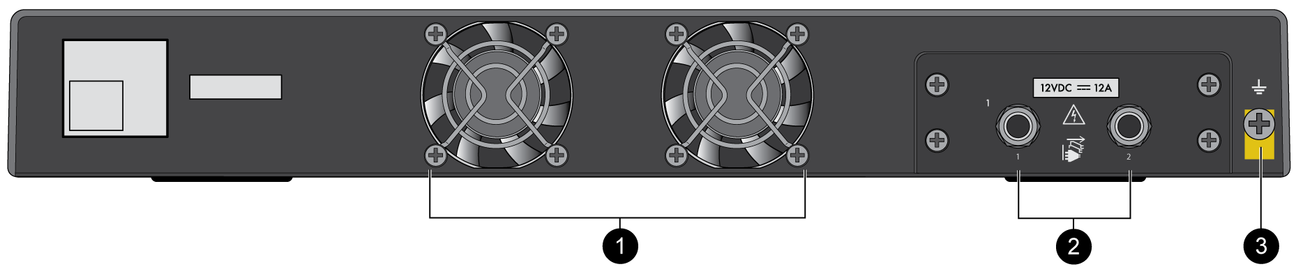
The following image shows the back panel of the PA-560.
The table describes each back panel component.
| Item | Component | Description |
|---|---|---|
|
1
|
Fans
|
Two single-rotor fans that provide cooling to the firewall. The fans
are not field replaceable.
|
|
2
|
Power Adapter Inputs
|
Two DC power inputs. One power supply is required, while a second
power supply can be used for redundancy.
|
|
3
|
Ground Stud
|
Use the single post ground stud to connect the firewall to earth
ground (ground cable not included).
|
PA-545-POE and PA-555-POE
View the front and back panel components of the PA-545-POE and PA-555-POE
firewalls.
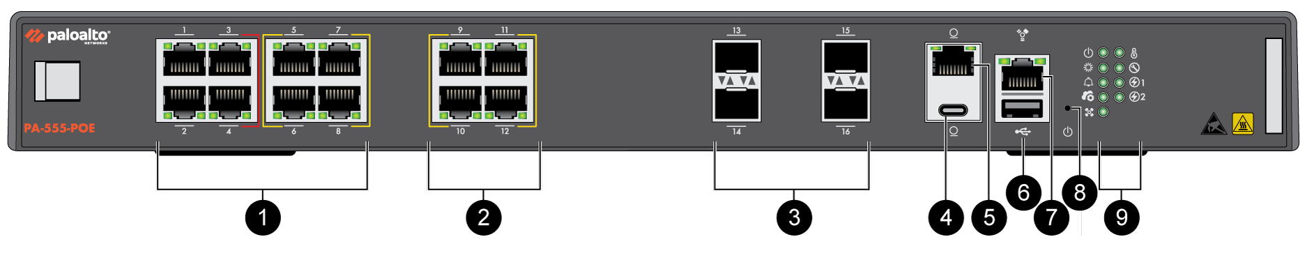
The following image shows the front panel
of the PA-545-POE and PA-555-POE, which have similar front panel components
(PA-555-POE pictured). The table describes each front panel component.
| Item | Component | Description |
|---|---|---|
|
1
|
RJ-45 Ports
|
Eight copper RJ-45 10Mbps/100Mbps/1Gbps ports for network
traffic.
Port 1 is a Zero Touch Provisioning (ZTP)
port. The ZTP port can be used to automatically provision the
firewall. Ports 3 and 4 are fail-open ports. They can be configured to
provide a pass-through connection despite power or operating
system failure. PA-545-POE
Ports 9 through 12 are Power over Ethernet (PoE) ports that can
transfer up to 181W of power to a connected device.
PA-555-POE
Ports 5 through 12 are Power over Ethernet (PoE) ports that can
transfer up to 332W of power to a connected device.
|
|
2
|
RJ-45 mGig Ports
|
PA-545-POE
Four RJ-45 mGig 1Gbps/2.5Gbps ports for network traffic. Ports 9
through 12 are Power over Ethernet (PoE) ports that can transfer up
to 181W of power to a connected device.
PA-555-POE
Four RJ-45 mGig 1Gbps/2.5Gbps ports for network traffic. Ports 5
through 12 are Power over Ethernet (PoE) ports that can transfer up
to 332W of power to a connected device.
|
|
3
|
SFP/SFP+ Ports
|
PA-545-POE
Four SFP 1Gbps ports for network traffic. (Ports 13 through 16)
PA-555-POE
Four SFP/SFP+ 1Gbps/10Gbps ports for network traffic. (Ports 13
through 16 support SFP; Ports 15 and 16 support SFP+)
|
|
4
|
Console port
(USB-C)
|
Use this port to connect a management computer to the firewall using
a standard USB-C cable.
The console connection provides access to firewall boot messages, the
Maintenance Recovery Tool (MRT), and the command line interface
(CLI).
|
|
5
|
Console port
(RJ-45)
|
Use this port to connect a management computer to the firewall using
a RJ-45 to USB cable and terminal emulation software.
The console connection provides access to firewall boot messages, the
Maintenance Recovery Tool (MRT), and the command line interface
(CLI).
Use the following settings to configure your terminal emulation
software to connect to the console port:
|
|
6
|
USB Port
|
One USB port for debugging and administration only. Use the port to
bootstrap the firewall.
Bootstrapping enables you to provision the firewall with a specific
PAN-OS configuration and then license it and make it operational on
your network.
In PAN-OS 12.2.2 and later versions, you can use this USB port to perform self-service enhanced factory reset (EFR). EFR provides remediation of a compromised or potentially compromised firewall to initiate a complete cleanup of the device. |
|
7
|
Management Port
|
Use this RJ-45 1Gbps port to access the management web interface and
perform administrative tasks. The firewall also uses this port for
management services, such as retrieving licenses and updating threat
and application signatures.
|
|
8
|
Reset Button
|
A pin press reset button that can be used to gracefully shut down the
firewall.
|
|
9
|
LED Status Indicators
|
Nine LEDs that indicate the status of the firewall hardware
components (see PA-500 Series Firewall LED Definitions).
|
The following image shows the back panel of the
PA-545-POE and PA-555-POE, which have similar back panel components. The table describes
each back panel component.

| Item | Component | Description |
|---|---|---|
|
1
|
Power Adapter Inputs
|
Two DC power inputs. One power supply is required, while a second
power supply can be used for redundancy.
|
|
2
|
Ground Stud
|
Use the single post ground stud to connect the firewall to earth
ground (ground cable not included).
|