PA-7500 Series Back Panel
Table of Contents
PA-7500 Series Back Panel
Learn about the back panel components of the PA-7500 Series Firewall.
The following image shows the back panel of the PA-7500 Series firewall and the table
describes each back panel component.

|
Item
|
Component
|
Description
|
|---|---|---|
|
1
|
Back slot cards
|
Two slots that house Switch Fabric Cards (SFCs). One SFC must be
installed while a second SFC can be installed for redundancy.
View the PA-7500 Series Module and Interface Card Descriptions for more
information on the slot cards and their components.
|
|
2
|
Fan assemblies
|
Up to fifteen fan assemblies that provide the appliance with cooling
and ventilation. The dual-rotor fan assemblies can be individually
replaced.
|
|
3
|
Ground stud
|
Two-post stud used to ground the appliance to earth ground. Use the
provided ground lug to connect a grounded cable to the two-post
stud.
|
|
4
|
Power inputs
(Only used with AC power supplies)
|
Ten power inputs that are only used when you install AC power
supplies. A chassis with low line input voltage (90V, 110/120V,
132V) requires a minimum of eight power supplies while a chassis
with high line input voltage (180V, 200/240V, 305V) requires a
minimum of four power supplies.
The minimum number of power supplies (four for high line and
eight for low line) are not enough to establish full power
redundancy in a fully loaded chassis. To provide full redundancy using high line power supplies, you
must install eight power supplies. A fully redundant power
configuration means that half of the installed power supplies
can fail and the appliance and all installed line cards still
function. On the back panel of the chassis, the power supplies are numbered as
follows:
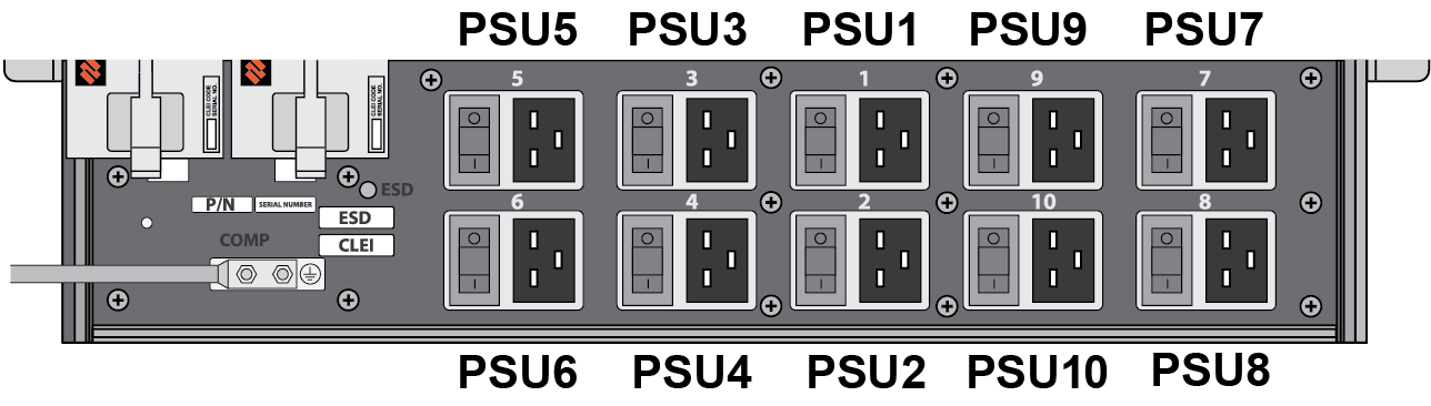
When you install DC power
supplies, the connectors and on/off switches on the back panel are
not used. For more information on connecting power to the firewall, see Connect Power to the PA-7500 Series Firewall.
|