PA-7500 Series Front Panel
Table of Contents
PA-7500 Series Front Panel
Learn about the front panel components of the PA-7500 Series Firewall.
The following image shows the front panel of the PA-7500 Series firewall (with AC power
supplies installed) and the table describes each front panel component.
To review the specifications of supported Palo Alto Networks®
interfaces and transceivers, refer to the datasheet.

|
Item
|
Component
|
Description
|
|---|---|---|
|
1
|
Front slot cards
|
Nine slots that house line cards to provide connectivity,
performance, and management functionality to the firewall.
From top to bottom, the chassis supports the following card(s) in
each slot:
View the PA-7500 Series Module and Interface Card Descriptions for more
information on the slot cards and their components.
|
|
2
|
Power supplies
|
Ten power supply slots that provide AC or DC power to the chassis. A
chassis with low line input voltage (90V, 110/120V, 132V) requires a
minimum of eight power supplies while a chassis with high line input
voltage (180V, 200/240V, 305V) requires a minimum of four power
supplies.
The minimum number of power supplies (four for high line and
eight for low line) are not enough to establish full power
redundancy in a fully loaded chassis. To provide full redundancy using high line power supplies, you
must install eight power supplies. A fully redundant power
configuration means that half of the installed power supplies
can fail and the appliance and all installed line cards still
function. On the front panel of the chassis, the power supplies are numbered as
follows:
AC power supplies 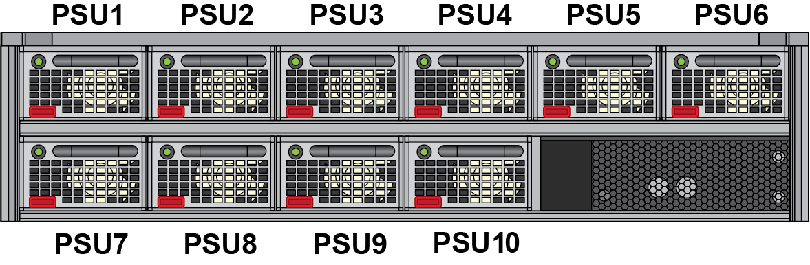
DC power supplies 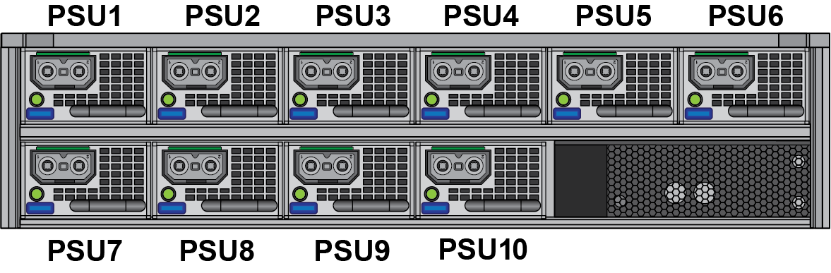
For more information on connecting power to the firewall, see Connect Power to the PA-7500 Series Firewall.
|