Prisma AIRS
Azure
Table of Contents
Expand All
|
Collapse All
Prisma AIRS Docs
Azure
Prisma AIRS AI Runtime: Network intercept post-deployment
configurations in Strata Cloud Manager and Azure to protect VM workloads and Kubernetes
clusters.
| Where Can I Use This? | What Do I Need? |
|---|---|
|
Configure Strata Cloud Manager
Interfaces
- Navigate to Configuration → NGFW and Prisma Access→ Device Settings → Interfaces.Set the Configuration Scope to your AI Runtime Security folder.Select Add Interface.
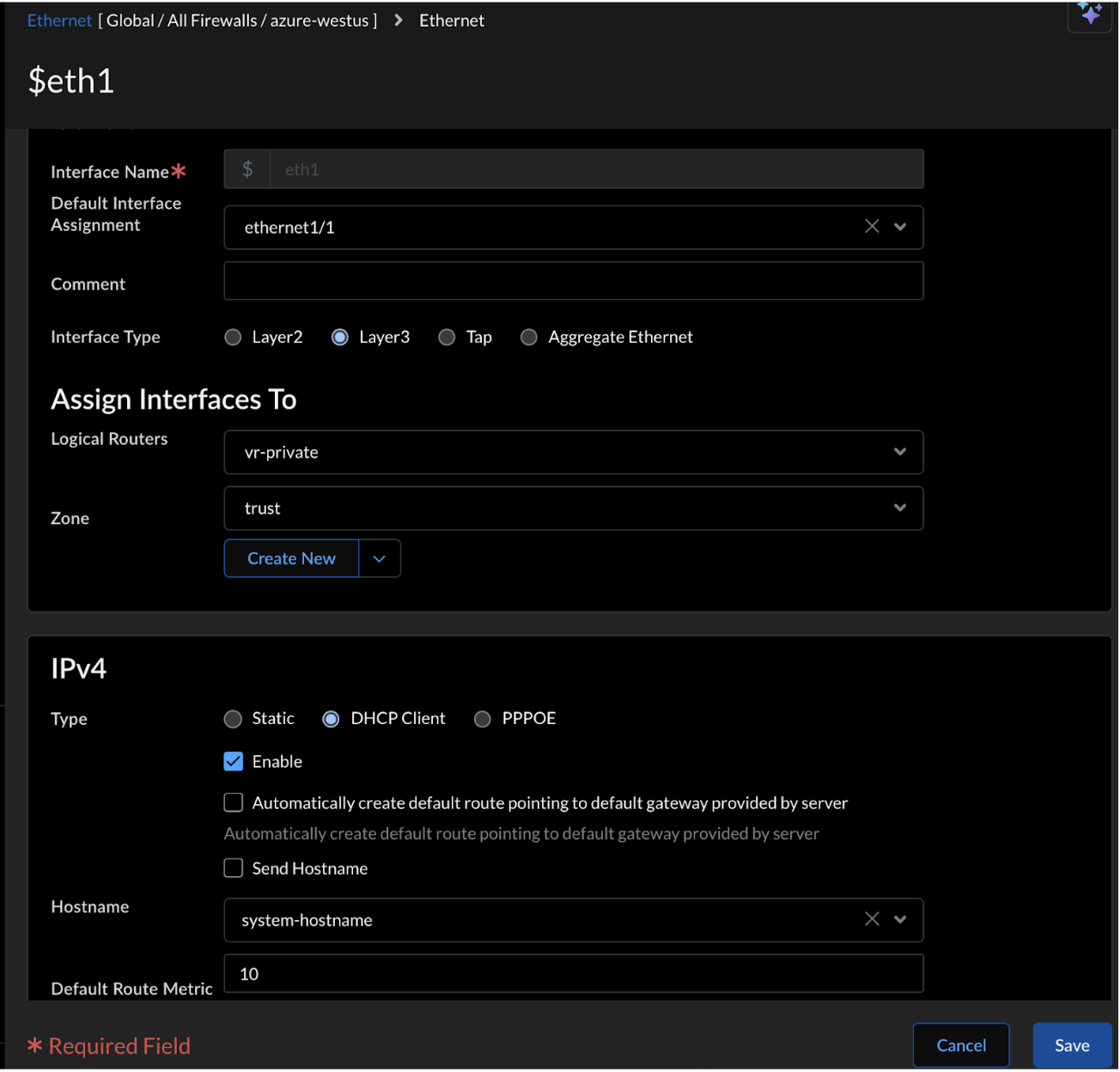
- In the Ethernet tab, configure a Layer 3 Interface for eth1/1(trust) and eth1/2(untrust):
- Enter Interface Name (Create interfaces for both eth1/1(trust) and eth1/2(untrust) interfaces).
- Select Layer3 Interface type.
- In Logical Routers, select `vr-private` for eth1/1 and `vr-public` for eth1/2.
- In Zone, select trust for eth1/1 and untrust for eth1/2.
- Select DHCP Client type under IPV4 address.
- Enable IPV4 for both eth1/1 and eth1/2 interfaces.
![]()
- For eth1/2 (untrust) only, enable Automatically create default route pointing to default gateway provided by server.
- Select Advanced Settings > Other Info.
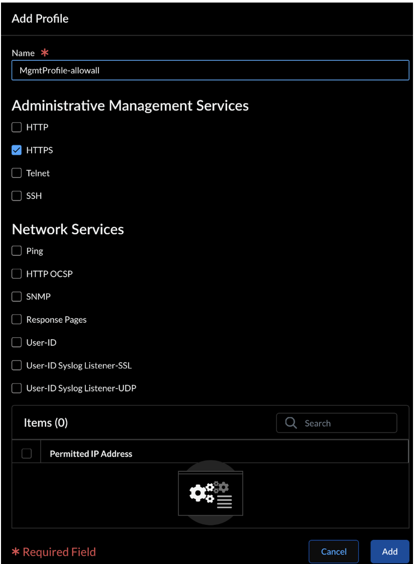
- Select a Management Profile or create a new one.In Administrative Management Services, enable HTTPS.
![]()
- Click Add.
- Select the Loopback tab to configure the Loopback interface to receive health checks from each load balancer:
- Select the Logical Routers.
- Set the trust Zone for private Logical Router and untrust Zone for the public Logical Router.
- In the IPv4s section, enter the private IP address of the Internal Load Balancer (ILB).This IP address is in the output displayed after successfully deploying the `security_project` Terraform, as described in the Deploy AI Runtime Security: Network Intercept in Azure page.
- Expand Advanced Settings → Management Profile and add your allow-health-checks profile.
- Add or Save.
Zones
- Navigate to Configuration → NGFW and Prisma Access→ Device Settings → Zones.
![]() Select Add Zone.Enter a Name.Select Layer3 Interface type.In Interfaces, add $eth1 interface for the trust zone and $eth2 interface for the untrust zone.Save.
Select Add Zone.Enter a Name.Select Layer3 Interface type.In Interfaces, add $eth1 interface for the trust zone and $eth2 interface for the untrust zone.Save.NAT
Configure the NAT policies for inbound and outbound traffic: - Navigate to Configuration → NGFW and Prisma Access → Network Policies → NAT.Configure NAT Policy for inbound traffic:
- Enter a Name indicating inbound traffic (for example, inbound-web).Original Packet:
- In Source zones, click add and select the untrust zone.
Destination:- Select trust Zone.
- Select any Interface.
- In Addresses, click the add (+) icon and select the public Elastic Load Balancer (ELB) address.
Choose any Service.Translated Packet:- In Translation, select Both.
- In Source Address Translation, select the Dynamic IP and Port translation type.
- In the choice, select Interface Address.
- In Interface, select eth1(ethernet1/1).
- In the Choice, select IP address.
- Set the Static IP address as the Translation Type.
- Select the destination Translated Address.
Save.Configure NAT Policy for Outbound traffic:- Enter a Name indicating outbound traffic (for example, outbound-internet).Original Packet:
- In Source zones, click add and select trust zone.
- In Addresses, click the add (+) icon and select the app-vnet and the Kubernetes pods CIDR you want to secure.
Destination:- Select the untrust destination zone.
- Select any interface.
Choose any Service.Translated Packet:- In Translation, select Source Address Only.
- In Source Address Translation, select the Dynamic IP and Port translation type.
- In choice, select Interface Address.
- In Interface, select eth2(ethernet1/2).
- In Choice, select IP address.
Save.Routers
Configure private and public virtual routers: Azure health probe fails with a single virtual router (VR). Create multiple VRs to ensure probe success.- Navigate to Configuration → NGFW and Prisma Access→ Device Settings → Routing.Enter a Name indicating private and public routers (for example, vr-private and vr-public).In Interfaces, select eth1(ethernet1/1) for the vr-private route and eth2(ethernet1/2)for the vr-public route.Refer to the above section on Interfaces to see how to configure the $eth1 and $eth2 interfaces.In Advanced Settings, select Edit to configure the IPV4 Static Routes for vr-private and vr-public.
- Select Add Static Route and add the following routes:Application routing:
- Enter a Name for example, app-vnet.
- In Destination, enter the CIDR address of your application.
- In Next Hop:
- For vr-private, in the IP Address
field, enter the gateway IP address of the private
interface (eth1/1).The gateway IP address is the first usable IP in the subnet's range (example, 192.168.1.1 for a /24 subnet). To find it, go to Azure Portal > Virtual Networks > [Your Virtual Network] > Subnets > [Private Subnet].
- For vr-public, in the Next Router field, enter `vr-public`.
- For vr-private, in the IP Address
field, enter the gateway IP address of the private
interface (eth1/1).
- In Interface, select eth1(ethernet1/1) subnet for `vr-private` and None for `vr-public`.
Default routing:- Enter a Name.
- In Destination, enter 0.0.0.0/0.
- In Next Hop:
- For vr-private, in the Next Router field, enter the `vr-private`.
- For vr-public, select IP Address . In the IP Address field, enter the gateway IP address of the vr-public interface (eth1/2).
- In Interface, choose None for `vr-private` and eth2(ethernet1/2) for `vr-public`.
- Click Add or Update.
Azure Load Balancer’s health probe:- Enter a Name.
- In Destination, enter the IP address of the Azure Load Balancer’s health probe (168.63.129.16/32).
- In Next Hop, select IP Address for
vr-private and vr-public.
- In IP Address, enter the gateway IP address of the corresponding interface.
- In Interface, select eth1(ethernet1/1) for vr-private and eth2(ethernet1/2) for vr-public.
Click Add.Click Save.Security Policy
- Log in to Strata Cloud Manager.Add a security policy (Configuration → NGFW and Prisma Access → Security Services → Security Policy → Add Rule).Set the action to Allow.Ensure the policy allows health checks from the Azure Load Balancer (LB) pool to the internal LB IP from Strata Cloud Manager. Check session IDs to ensure the firewall responds correctly on the designated interfaces.
Configurations to Secure VM Workloads
- Log in to Strata Cloud Manager.Configure routes for vNet endpoints as explained in the Routers section above to ensure a route to your application.Navigate to Configuration → Push Config and push the policy configurations to your Prisma AIRS AI Runtime: Network intercept.Create or update the NAT policy (refer to the NAT section above) to secure the VM workloads. Set the source address of the application you want to secure.
Configurations to Secure Kubernetes Clusters
- Log in to Strata Cloud Manager.Configure static routes (refer to the routes section above) on the Logical Router for Kubernetes workloads.Below are the configurations for pod and service subnets static routes for the Kubernetes workloads:
- Pod Subnet and Service subnet for vr-private:
Route Type Name Destination Next Hop Next Hop Value Interface Pod subnet pod_route Pod IPV4 range CIDR IP Address Subnet Gateway IP address eth1(ethernet1/1) Service subnet service_route 172.16.0.0/24 IP Address Subnet Gateway IP address eth1(ethernet1/1) - Pod Subnet and Service subnet for vr-public:
Route Type Name Destination Next Hop Next Hop Value Interface Pod subnet pod_route Pod IPV4 range CIDR Next Router vr-public None Service subnet service_route 172.16.0.0/24 Next Router vr-public None
Refer to the NAT policy in the above section to secure the Kubernetes clusters and set the source address of the Kubernetes pods CIDR you want to secure.Navigate to Configuration → Push Config and push the policy configurations to Prisma AIRS AI Runtime: Network intercept.Secure a Kubernetes Application with Helm
This section covers how to install and configure the Helm chart to secure your Kubernetes applications based on the protection level you selected during deployment. The Helm chart installation process and directory structure vary depending on whether you selected VPC-level protection or namespace-level protection with traffic steering inspection. VPC-level protection secures all applications within the VPC, while namespace-level protection with traffic inspection provides granular control over specific application traffic flows and CIDR-based inspection rules.Your deployment configuration determines the specific Helm chart structure and commands required for your environment..- Navigate to the downloaded tar file and extract the contents:tar -xvzf <your-terraform-download.tar.gz>Navigate to the appropriate Helm directory based on your deployment configuration:
- For VPC-level
security:cd <unzipped-folder>/architecture/helm
- For namespace-level security with traffic steering inspection:
cd <unzipped-folder>/architecture/helm-<complete-app-name-path>Navigate to each Helm application folder. When you configure traffic steering inspection, separate Helm charts are generated for each protected namespace, allowing granular security policies per application.Install the Helm chart using the appropriate command:- For VPC-level
security:helm install ai-runtime-security helm --namespace kube-system --values helm/values.yaml
- For namespace-level security with traffic steering inspection:
Repeat this command for each namespace-specific Helm chart generated during the deployment process.helm install ai-runtime-security helm-<complete-app-name-path> --namespace kube-system --values helm-<complete-app-name-path>/values.yamlEnable "Bring your own Azure virtual network" to discover Kubernetes-related vnets:- In Azure Portal, navigate to Kubernetes services → [Your Cluster]→ Settings→ Networking.
- Under Network configuration, select Azure CNI as the Network plugin, then enable Bring your own Azure virtual network.
This creates a container network interface (CNI), but doesn’t protect the container traffic until you annotate the application `yaml` or `namespace`.Verify the Helm installation:#List all Helm releases helm list -A #Ensure the output shows your installation with details such as: NAME NAMESPACE REVISION UPDATED STATUS CHART APP VERSION ai-runtime-security kube-system 1 2024-08-13 07:00 PDT deployed ai-runtime-security-0.1.0 11.2.2Check the pod status:kubectl get pods -A #Verify that the pods with names similar to `pan-cni-*****` are present.Check the endpoint slices:kubectl get endpointslice -n kube-system #Confirm that the output shows an ILB IP address: NAME ADDRESSTYPE PORTS ENDPOINTS AGE my-endpointslice IPv4 80/TCP 10.2xx.0.1,10.2xx.0.2 12hVerify the Kubernetes resources were created properly:a. Check the service accounts kubectl get serviceaccounts -n kube-system | grep pan b. Check the secrets kubectl get secrets -n kube-system | grep pan c. Check the services: `kubectl get svc -n kube-system | grep pan`You should see resources like pan-cni-sa (service accounts), pan-plugin-user-secret (secrets), and pan-ngfw-svc (service).Annotate at the pod level in your application yaml so that the traffic from the pod is redirected to the Prisma AIRS AI Runtime: Network intercept for inspection.Annotate the pod using the below command:- For VPC-level
security:kubectl annotate namespace <namespace-to-be-annotated> paloaltonetworks.com/firewall=pan-fw
- For namespace-level security with traffic steering inspection:
Ensure every pod has this annotation to be moved to the ‘protected’ state across all cloud environments.kubectl annotate pods --all paloaltonetworks.com/subnetfirewall=ns-secure/bypassfirewallRestart the existing application pods after applying Helm and annotating the pods for all changes to take effect. This enables the firewall to inspect the pod traffic and secure the containers. - For namespace-level security with traffic steering inspection:
- For namespace-level security with traffic steering inspection:
- For namespace-level security with traffic steering inspection:


