Connect AC or DC Power to a PA-5400 Series Firewall
Table of Contents
Connect AC or DC Power to a PA-5400 Series Firewall
Connect an AC or DC power source to a PA-5400 Series
firewall after determining which boot mode to launch the appliance
in.
The following procedure describes how to connect power to a PA-5410, PA-5420, PA-5430, PA-5440, and PA-5445 firewall with either AC or DC power
supplies installed. The AC power supplies support 100 to 240VAC power input and the
DC power supplies support 48 to 60VDC power input.
Learn how to Set Up a Connection to the Firewall based on your desired
boot mode prior to powering on the firewall for the first time.
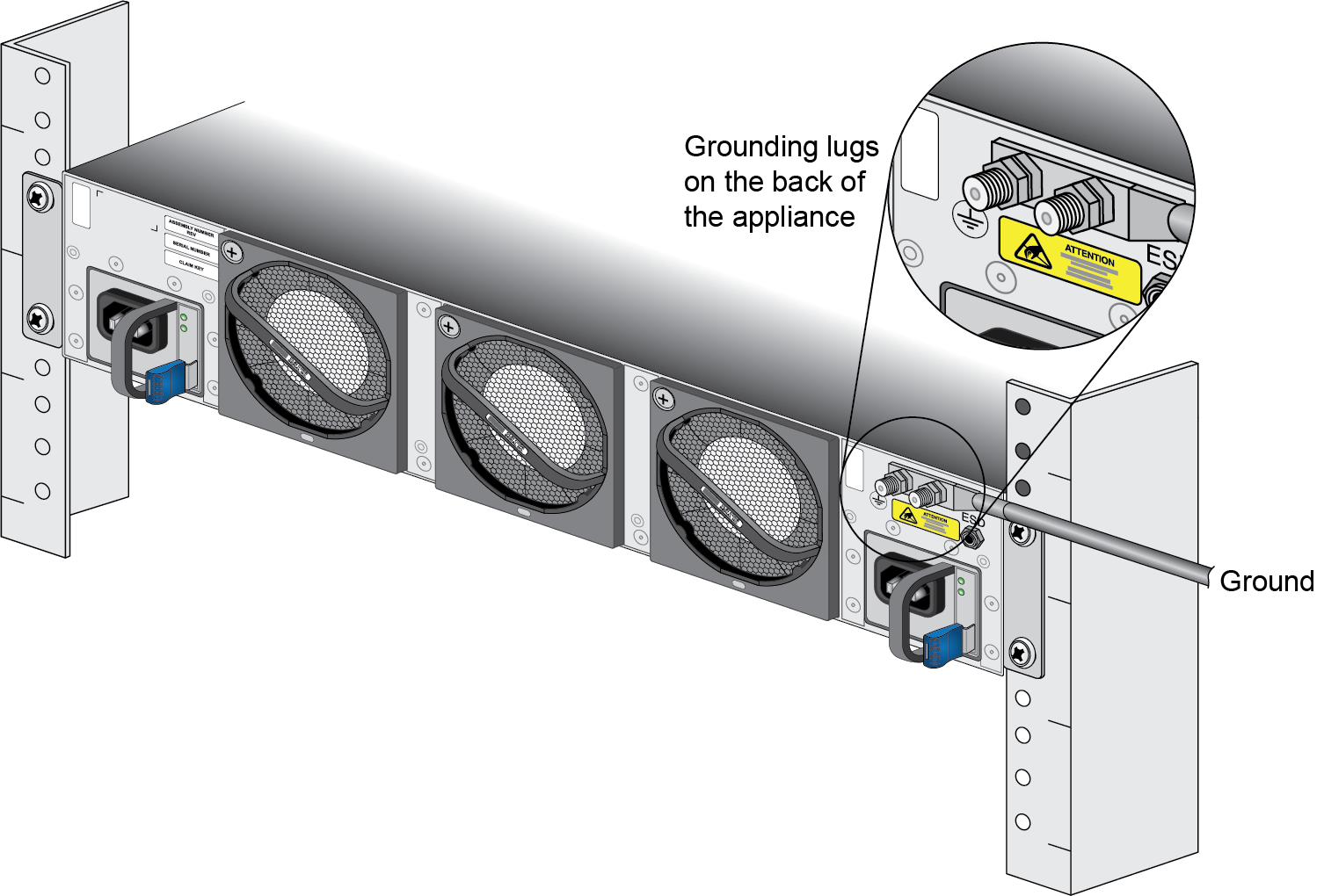
- Read Product Safety Warnings.Put the provided ESD wrist strap on your wrist ensuring that the metal contact is touching your skin. Then attach (snap) one end of the ground cable to the wrist strap and remove the alligator clip from the banana clip on the other end of the ESD grounding cable. Plug the banana clip end into one of the ESD ports located on the back of the appliance before handling ESD sensitive hardware. For details on the ESD port location, see PA-5400 Series Back Panel.For DC deployments, ensure that your DC power feed is powered off.Remove the four nuts from the ground studs located on the back of the appliance on the upper left side.
![]() Crimp a 6-AWG wire to the provided grounding lug and connect the other end to your earth ground point.The crimp tool is not included with the appliance. It is recommended that you use a Panduit CT-3001/ST crimp tool for this procedure. Refer to the manufacturer’s specifications for more information.Connect the two-post lug connector to the two-post ground studs on the appliance using the provided nuts and torque each nut to 50 in-lbs. Be careful not to strip the nuts and lug studs.Connect the power supply to a power source based on whether your power supplies are AC or DC.(AC Power Supplies only)
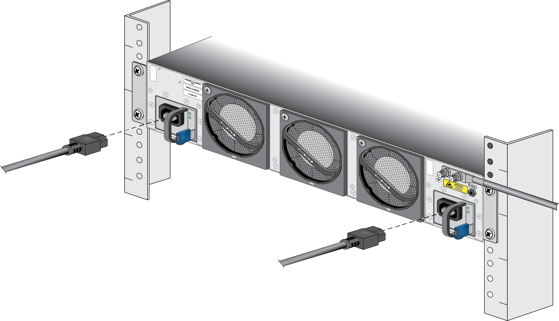
Crimp a 6-AWG wire to the provided grounding lug and connect the other end to your earth ground point.The crimp tool is not included with the appliance. It is recommended that you use a Panduit CT-3001/ST crimp tool for this procedure. Refer to the manufacturer’s specifications for more information.Connect the two-post lug connector to the two-post ground studs on the appliance using the provided nuts and torque each nut to 50 in-lbs. Be careful not to strip the nuts and lug studs.Connect the power supply to a power source based on whether your power supplies are AC or DC.(AC Power Supplies only)- Connect the first two power supplies to a 120VAC 15-amp circuit breaker or 240VAC 20-amp circuit breaker using the provided power cords and then connect the second two power supplies to a second, independent 120VAC 15-amp circuit breaker or 240VAC 20-amp circuit breaker.
![]()
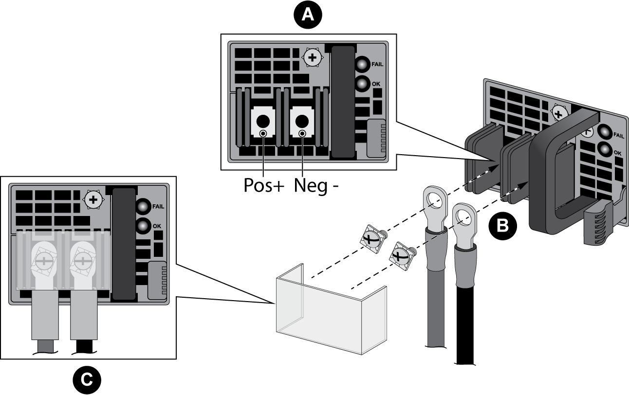
(DC Power Supplies only)- Remove the plastic DC power input cover from each of the two DC power supplies and then remove the positive and negative terminal screws.
- Crimp ring lugs to the ends of the DC cables. These lugs are used to connect the DC cables to the DC inputs on the firewall.
- Use the DC terminal screws to connect a positive (red) DC power cable to the positive terminal on the first DC power supply and then connect a negative (black) DC power cable to the negative terminal. Repeat this step for the second DC power supply using separate positive and negative cables.
- Replace the plastic covers over each DC power input.
- Connect the two positive and two negative DC power cables to your power source, ensuring that you observe the correct polarity (positive to positive and negative to negative).
![]()
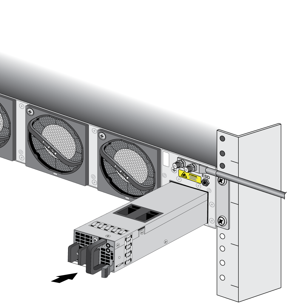
![]() When cabling the DC power supply to your power source, ensure that you route the cable in such a way that it does not put pressure on the plastic clips located at the front of the DC power supplies. It is best to route the cables first and then plug the cables into the power supplies.Secure the power cords to the power inlets using the velcro straps.
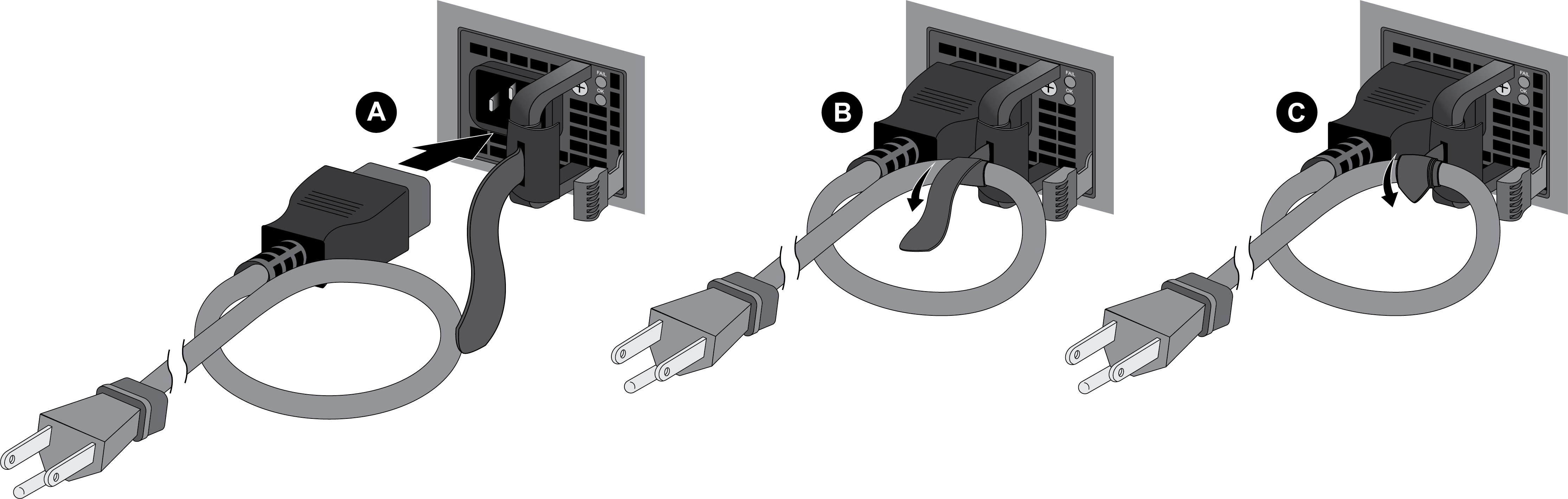
When cabling the DC power supply to your power source, ensure that you route the cable in such a way that it does not put pressure on the plastic clips located at the front of the DC power supplies. It is best to route the cables first and then plug the cables into the power supplies.Secure the power cords to the power inlets using the velcro straps.![]() After each AC or DC cable is securely connected, turn on the power source and the appliance will power on.Before powering on the firewall, ensure that you have connected your Ethernet cables in accordance to the mode you wish to boot the firewall in (standard mode or Zero Touch Provisioning mode) as specified in Set Up a Connection to the Firewall.
After each AC or DC cable is securely connected, turn on the power source and the appliance will power on.Before powering on the firewall, ensure that you have connected your Ethernet cables in accordance to the mode you wish to boot the firewall in (standard mode or Zero Touch Provisioning mode) as specified in Set Up a Connection to the Firewall.