Download PDF
Interpret the PA-5400 NC-A LEDs
Table of Contents
Expand all | Collapse all
Interpret the PA-5400 NC-A LEDs
Learn how to interpret the PA-5400 NC-A LEDs to monitor
the status of the card.
Use the following information to learn how to interpret
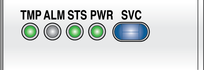
the LED dashboard and port LEDs on the PA-5400 Networking Card (NC-A)

The following table describes the functions and states of the
NC-A LED dashboard.
LED | State | Description |
|---|---|---|
TMP (Temperature) | Green | The card temperature is normal. |
Yellow | The card temperature is outside
the temperature tolerance. | |
ALM (Alarm) | Red | The card hardware failed. |
Off | The card is operating normally. | |
STS (STATUS) | Green | The card is operating normally. |
Yellow | The card is booting up. | |
PWR | Green | The card is powered on. |
Off | The card is powered off. | |
SVC (Service) | Allows a remote administrator
to illuminate the SVC LED on a specific front-slot card so an on-site
technician can locate the card. Enter the following command
to view the status of the SVC LED on all cards that have this LED: admin@PA-5450> show system service-led status
Service LED
Slot Description Status
s1 PA-5400-NC-A On
s2 empty Off
s3 PA-5400-DPC-A On
s4 empty Off
s5 empty Off
s6 empty Off
s7 PA-5400-MPC-A On
| |
SVC (Continued) | Enter the following command
to view the status for a card in a specific slot: admin@PA-5450> show system service-led status slot s3Enter
the following command to enable all SVC LEDs: admin@PA-5450>set system setting service-led enable yesEnter
the following command to disable the SVC LED: admin@PA-5450> set system setting service-led enable noEnter
the following command to enable the SVC LED on the card in a specific
slot: admin@PA-5450> set system setting service-led enable slot s3 yes | |
Off | LED is off. | |
On | LED is solid blue. | |
The following table describes functions and states of the SFP+
port LEDs.
LED | Description |
|---|---|
| Left | The LED shows green if there is a network
link. |
| Right | Blinks green or stays green if there is
network activity. |
The following table describes functions and states of the QSFP28
port LEDs. The LEDs are tri-color and the color indicates link and
the current port speed.
Interface Speed | Green LED | Blue LED | Yellow LED |
|---|---|---|---|
10Gbps | On | Off | Off |
25Gbps | On | On | Off |
40Gbps | Off | Off | On |
100Gbps | Off | On | Off |
