Connect Ethernet Cables to the PA-400R Series Firewall
Table of Contents
Connect Ethernet Cables to the PA-400R Series Firewall
Learn how to connect Ethernet cables to the PA-400R Series Firewall and install the
secure panel.
This topic describes how to connect Ethernet cables to the PA-410R, PA-455R-5G, and PA-410R-5G firewall using cable
glands.
(PA-410R and PA-410R-5G only) The
PAN-PA-RGD-GLND1 includes one M20 (for one power cable) and three M12 glands
(for three RJ-45 cables). It must be purchased separately.
(PA-455R-5G only) Use this procedure for guidance on
connecting other cables too, such as USB and SFP cables.
The management and console cables are only for initial deployment
and are not intended for installation with the cable glands. Ensure that you
have completed onboarding your firewall, then disconnect the management and
console cables before beginning this procedure.
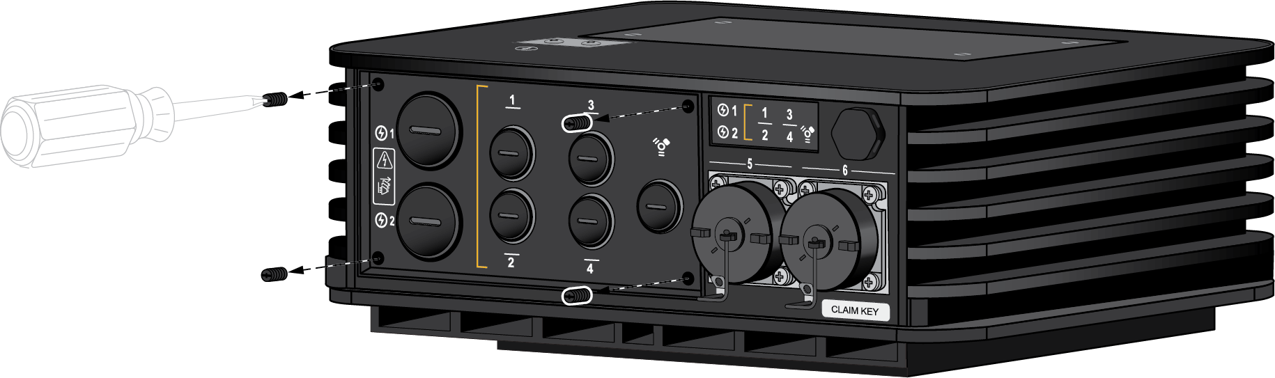
- Unscrew the four screws on the bottom panel of the firewall.
- PA-410R and PA-410R-5G—Use a flathead screwdriver.
![]()
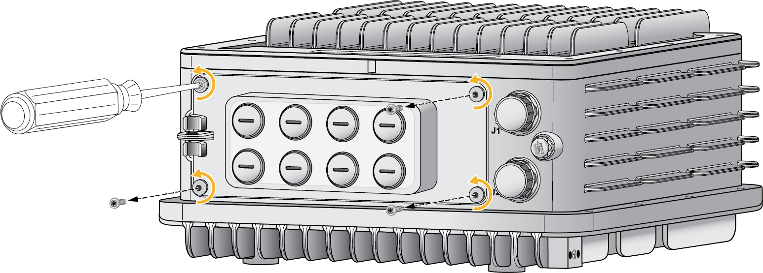
- PA-455R-5G—Use a T20 security bit or
screwdriver.
![]()
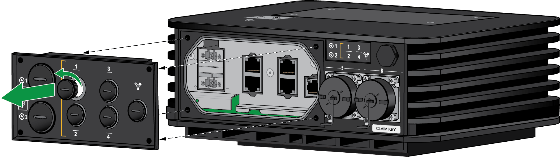
On the removed panel, unscrew the stopping plug that lines up with the Ethernet port you are connecting to.- PA-410R and PA-410R-5G—Each stopping plug corresponds to one
Ethernet port.
![]()
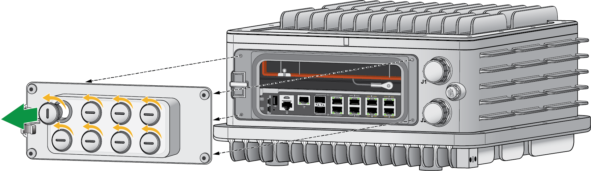
- PA-455R-5G—Some stopping plugs may have to
be used for more than one cable. Plan accordingly by purchasing the
appropriate cable glands and cables.
![]()
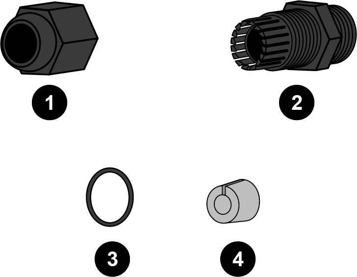
Unpack the cable glands.- PA-410R and PA-410R-5G—You must have either purchased
PAN-PA-RGD-GLND1 or acquired other standard M12 cable glands. There are
four necessary items — an end cap, panel connector, seal, and
grommet.
![]()
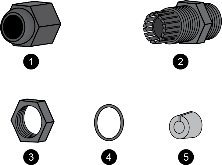
- PA-455R-5G—You must have acquired standard
M20 cable glands that are IP65 rated at minimum. There are five
necessary items — an end cap, panel connector, nut, seal, and
grommet.
![]()
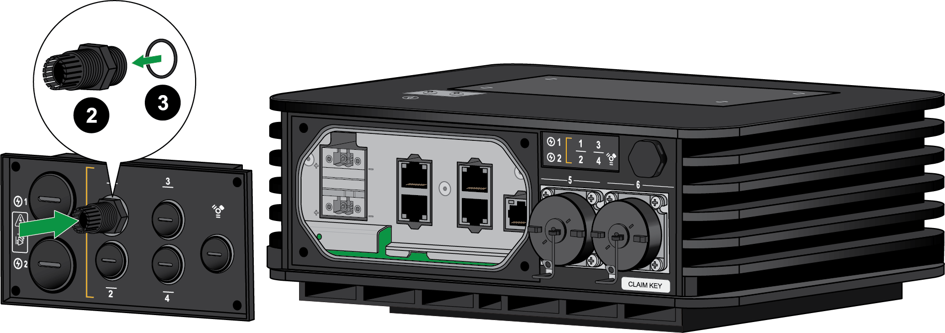
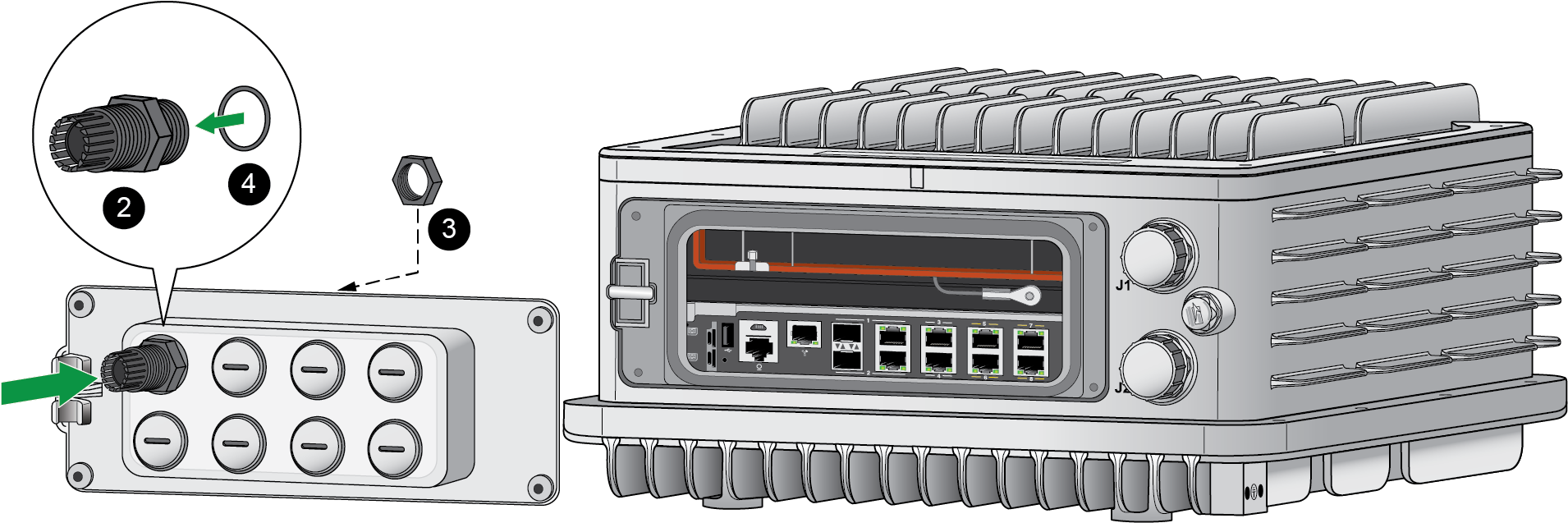
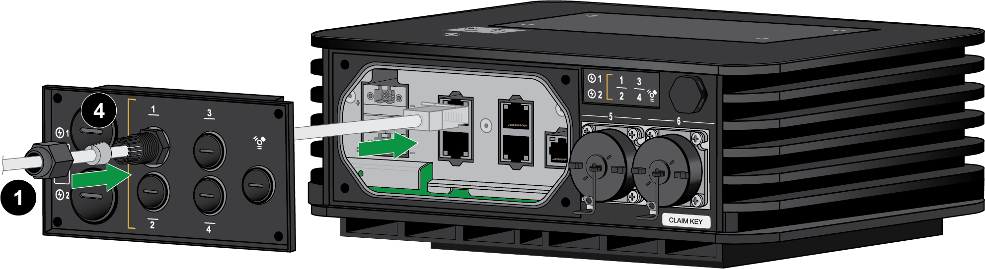
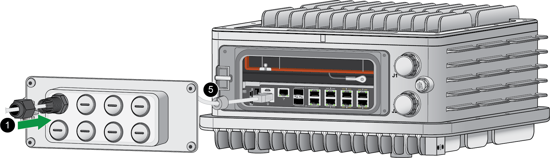
Install the seal onto the shorter end of the panel connector. Make sure to push the seal until it is flush against the nut. Screw the shorter end of the panel connector into the hole that corresponds to the port being connected. Make sure that the connector is secure by torquing to 1.5 Nm.PA-410R and PA-410R-5G![]() PA-455R-5G
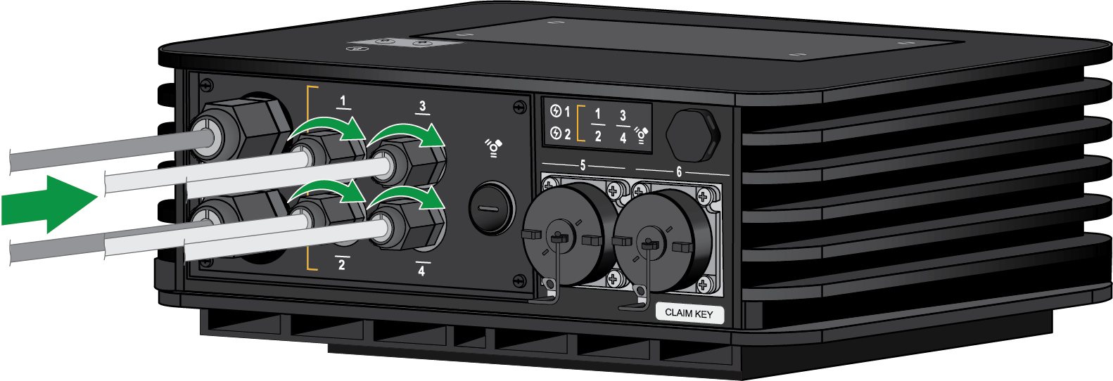
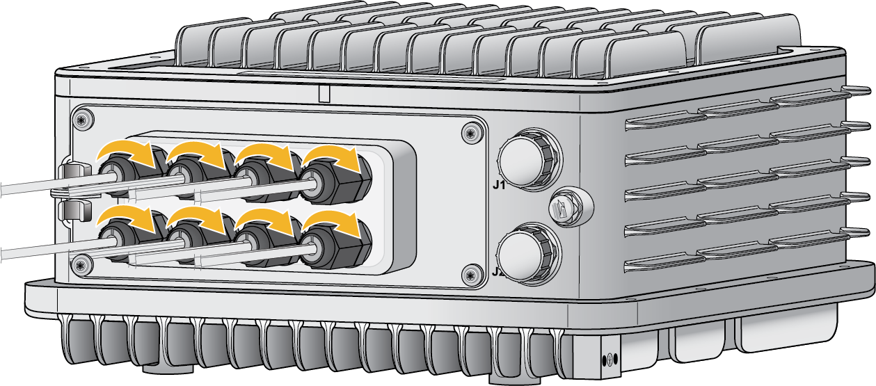
PA-455R-5G![]() Thread the cable through the end cap. This is used to secure the cable gland once the panel is reattached at the end of the procedure. Feed the cable through the gray grommet. Move the cable through the panel connector and gently push the end into the port until you hear a click.PA-410R and PA-410R-5G
Thread the cable through the end cap. This is used to secure the cable gland once the panel is reattached at the end of the procedure. Feed the cable through the gray grommet. Move the cable through the panel connector and gently push the end into the port until you hear a click.PA-410R and PA-410R-5G![]() PA-455R-5G
PA-455R-5G![]() Repeat Steps 4 and 5 for any additional cables.(PA-410R and PA-410R-5G only) Follow the procedure to Connect DC Power to a PA-400R Series Firewall before you continue to the next step.Once all cables are connected, make sure that any unused ports have a stopping plug in the corresponding panel slot.
Repeat Steps 4 and 5 for any additional cables.(PA-410R and PA-410R-5G only) Follow the procedure to Connect DC Power to a PA-400R Series Firewall before you continue to the next step.Once all cables are connected, make sure that any unused ports have a stopping plug in the corresponding panel slot.- PA-410R and PA-410R-5G—Ensure that all Ethernet and power cables are connected before continuing to the next step.
- PA-455R-5G—Ensure that all Ethernet, SFP, and USB cables are connected before continuing to the next step.
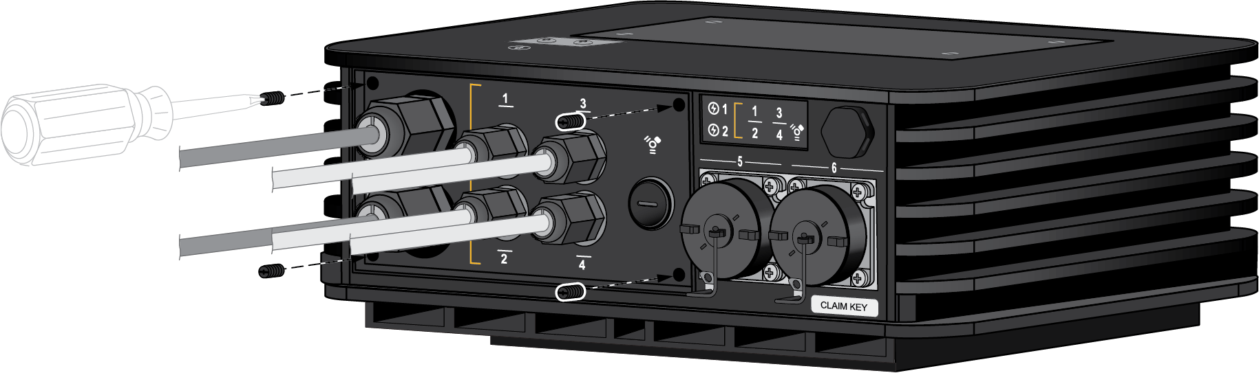
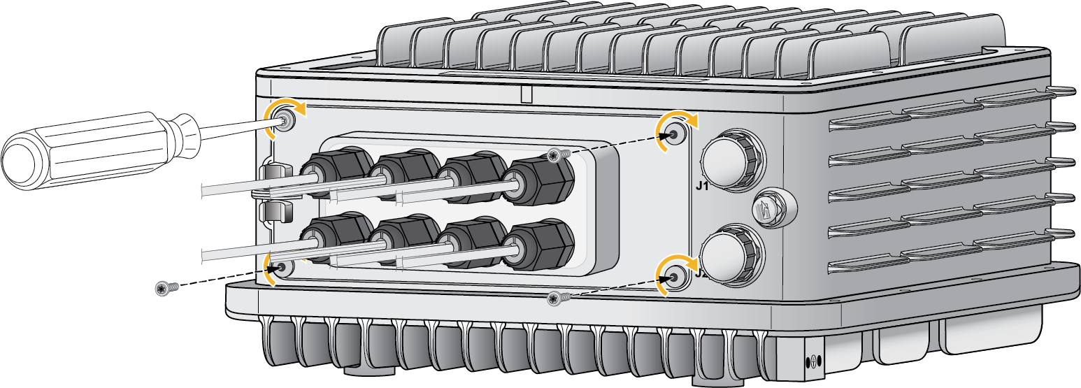
Align the panel with the four screw holes on the firewall. Using the appropriate screwdriver, screw the panel back into its original place.- PA-410R and PA-410R-5G
![]()
- PA-455R-5GTorque the four screws to 21nm (16±1 in-lbs).
![]()
Push the end caps along each cable until the end caps reach their respective panel connector.- PA-410R and PA-410R-5G
![]()
- PA-455R-5G
![]()

- PA-410R and PA-410R-5G—Use a flathead screwdriver.