Connect DC Power to a PA-400R Series Firewall
Table of Contents
Connect DC Power to a PA-400R Series Firewall
Power the PA-410R, PA-410R-5G, PA-450R-5G, and PA-450R firewalls with
DC power.
The following procedure describes how to connect DC power to a
PA-410R , PA-410R-5G, PA-450R-5G, and PA-450R firewall. Before you continue, read how to Prepare to Connect Power to a PA-400R Series Firewall. The DC terminal block for connecting the DC power
cables to the firewall is included in the accessories kit.
The PA-410R and PA-410R-5G firewalls
use cable glands (purchased separately) to waterproof the inside of the device. The
PAN-PA-RGD-GLND1 includes one M20 (for one power cable) and three M12 glands (for
three RJ-45 cables).
To avoid injury to yourself or damage to your Palo Alto Networks® hardware or the
data that resides on the hardware, read the Safety Warnings.
Power off the DC power sources that you will connect to the power supplies before
you continue.
- Verify that the DC power source that will power the firewall is powered off.In the following procedure, connect the DC power cables—and ground cable if you do not use the screw-on ground point—to the DC terminal block before you attach the DC terminal block to the firewall.(PA-410R and PA-410R-5G only) Prepare to install the power cables using cable glands.
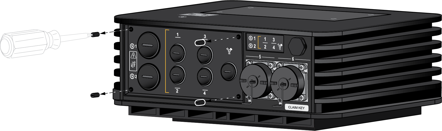
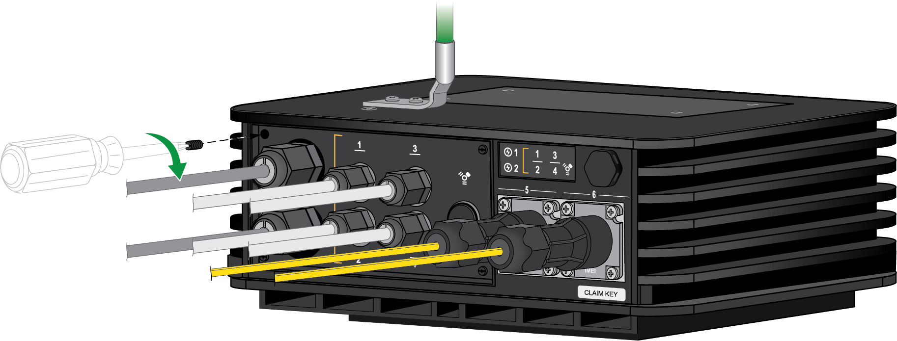
- Using a Phillips-Head screwdriver, unscrew the four screws on the bottom panel of the firewall.
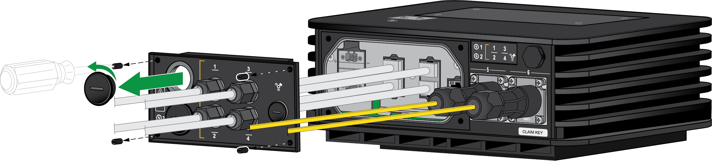
![]() On the removed panel, unscrew the stopping plug that lines up with the DC power input you are connecting to.
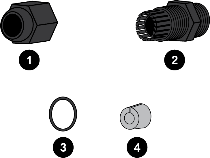
On the removed panel, unscrew the stopping plug that lines up with the DC power input you are connecting to.![]() Unpack the power cable glands. There are four items — an end cap, panel connector, lock nut, and seal.
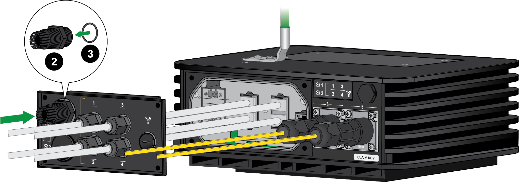
Unpack the power cable glands. There are four items — an end cap, panel connector, lock nut, and seal.![]() Loop the seal onto the shorter end of the panel connector. Make sure to push the seal until it is flush against the nut. Screw the shorter end of the panel connector into the hole that corresponds to the DC power input being connected. Make sure that the connector is secure.
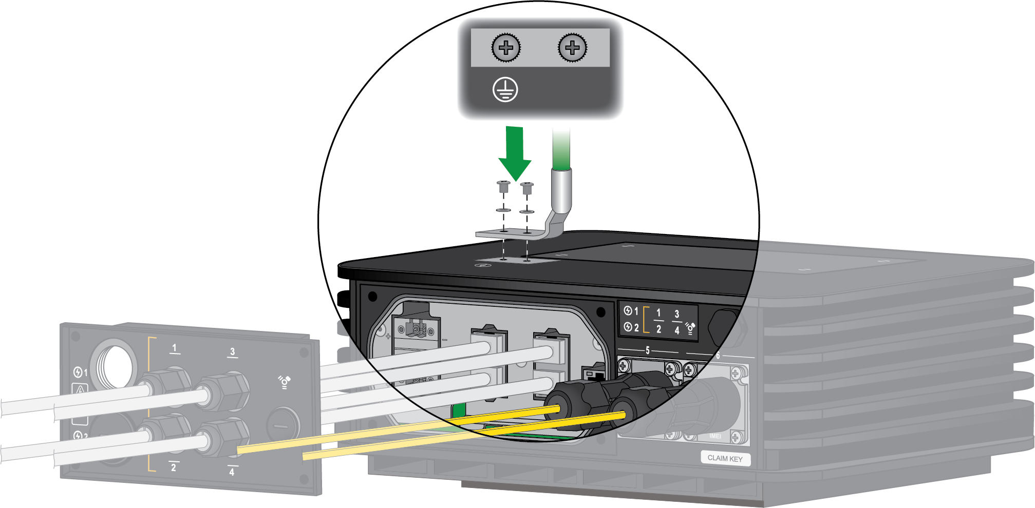
Loop the seal onto the shorter end of the panel connector. Make sure to push the seal until it is flush against the nut. Screw the shorter end of the panel connector into the hole that corresponds to the DC power input being connected. Make sure that the connector is secure.![]() Thread the power cable through the end cap. This is used to secure the cable gland once the panel is reattached at the end of the procedure.Connect one end of a 8 AWG ground cable (not included) to the dual-hole ground lug. Connect the other end of the cable to earth ground. Remove the two ground screws from the ground point on the front panel of the firewall. Hold the ground lug (that you previously attached to the ground cable) over the screw holes, and then re-attach the screws to secure the cable to the firewall. Do not torque the screws to more than 6 in-lbs.
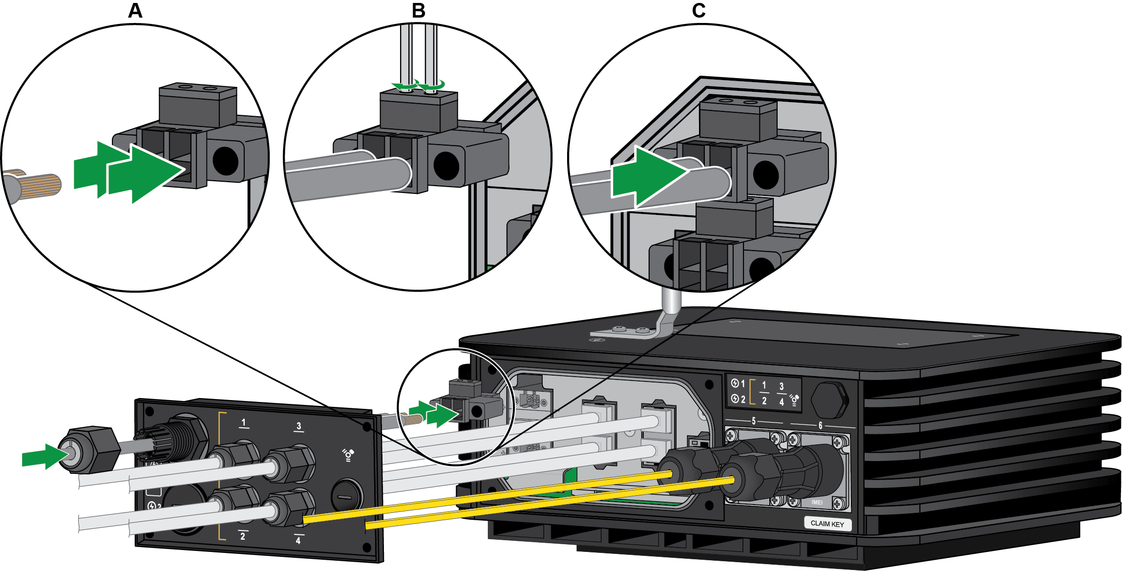
Thread the power cable through the end cap. This is used to secure the cable gland once the panel is reattached at the end of the procedure.Connect one end of a 8 AWG ground cable (not included) to the dual-hole ground lug. Connect the other end of the cable to earth ground. Remove the two ground screws from the ground point on the front panel of the firewall. Hold the ground lug (that you previously attached to the ground cable) over the screw holes, and then re-attach the screws to secure the cable to the firewall. Do not torque the screws to more than 6 in-lbs.![]() (PA-410R and PA-410R-5G only) Thread the power cable through the hole in the removed bottom panel that corresponds to the power inputs.Insert the positive and negative DC cables into the connector. The connector supports 12 to 30 AWG cables, but 16 AWG is recommended. Secure each cable using a 1/8” flat head screwdriver. Turn the connector screws clockwise until tight. Do not torque the screws to more than 2 in-lbs.
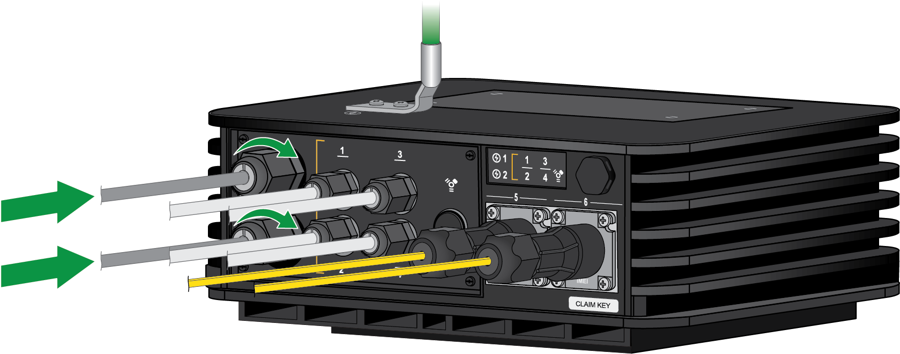
(PA-410R and PA-410R-5G only) Thread the power cable through the hole in the removed bottom panel that corresponds to the power inputs.Insert the positive and negative DC cables into the connector. The connector supports 12 to 30 AWG cables, but 16 AWG is recommended. Secure each cable using a 1/8” flat head screwdriver. Turn the connector screws clockwise until tight. Do not torque the screws to more than 2 in-lbs.![]() Plug the cabled DC connector into the DC input on the firewall. Secure the connector by turning the two screws on each side clockwise and torque them to 3 in-lbs.(Optional) Connect a second DC cable for redundancy.(PA-410R and PA-410R-5G only) Follow the procedure to Connect Ethernet Cables to the PA-400R Series Firewall before you screw the bottom panel back into place.
Plug the cabled DC connector into the DC input on the firewall. Secure the connector by turning the two screws on each side clockwise and torque them to 3 in-lbs.(Optional) Connect a second DC cable for redundancy.(PA-410R and PA-410R-5G only) Follow the procedure to Connect Ethernet Cables to the PA-400R Series Firewall before you screw the bottom panel back into place.- Once all Ethernet and power cables are connected, make sure that any unused ports have a stopping plug in the corresponding panel slot.Align the panel with the four screw holes on the firewall. Using a Phillips-Head screwdriver, screw the panel back into its original place.
![]() Push the end caps along each Ethernet and power cable until the end caps reach their respective panel connector. Screw the end caps onto each panel connector, making sure that it is tight and secure.
Push the end caps along each Ethernet and power cable until the end caps reach their respective panel connector. Screw the end caps onto each panel connector, making sure that it is tight and secure.![]() Power on the DC power source to power on the firewall. The firewall powers on and the power LED turns green.
Power on the DC power source to power on the firewall. The firewall powers on and the power LED turns green.