PA-400R Series Top and Bottom Panels
Table of Contents
PA-400R Series Top and Bottom Panels
Learn about the PA-400R Series firewall top and bottom panel components.
View the top and bottom panel components of your PA-400R Series firewall.
The PA-410R and PA-410R-5G firewalls
feature serviceable components on the top and bottom panels.
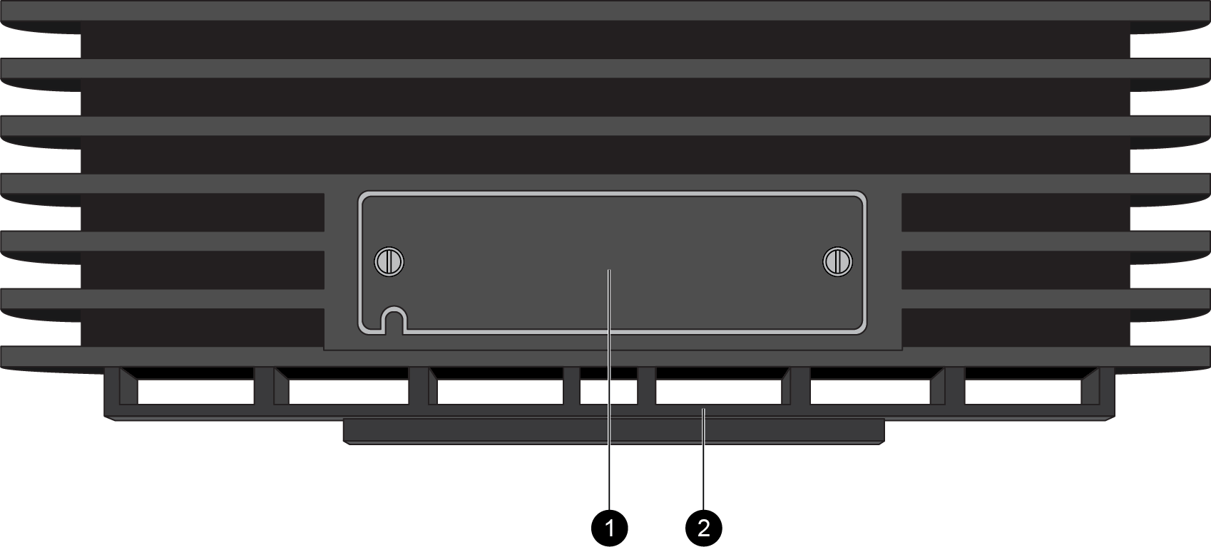
The top panels of the PA-410R and PA-410R-5G
are identical. The following image shows the top panel of the PA-410R and the
table describes each back panel component.
| Item | Component | Description |
|---|---|---|
|
1
|
SIM slot
|
After removing the cover, install up to two nano SIM cards into this
slot to enable multiple mobile network connectivity.
The nano SIM cards installed must be
industrial grade and rated to 105C. |
|
2
|
DIN rail mounting clip
|
Use this mounting clip to Install the PA-400R Series Firewall on a DIN Rail
|
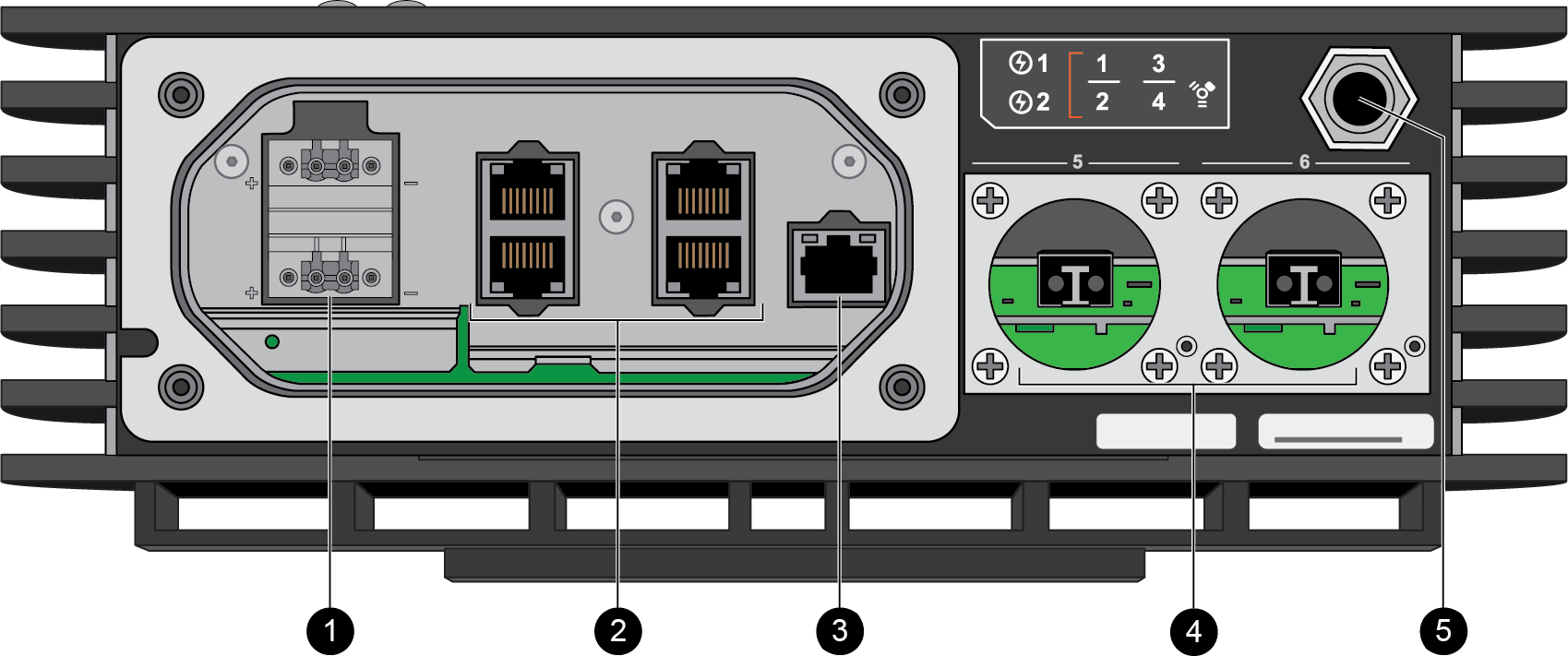
The bottom panels of the PA-410R and PA-410R-5G are identical
except that the PA-410R-5G features antennas. The following image shows the
bottom panel of the PA-410R after the cover and caps have been removed and the table
describes each bottom panel component.
| Item | Component | Description |
|---|---|---|
|
1
|
DC Power Inputs
|
The firewall operates on 12-48VDC power. Use the DC power inputs to
connect power to the firewall. A second, optional power supply can
be used for redundancy.
|
|
2
|
RJ-45 Ports
|
Four RJ-45 10/100/1000Mbps ports for network traffic.
You can set the link speed and duplex mode or choose
auto-negotiate.
Ports 1 and 2 are fail-open ports. They can be configured to provide
a pass-through connection despite power or operating system
failure.
|
|
3
|
Management port
|
Use this Ethernet 1Gbps port to access the management web interface
and perform administrative tasks. The firewall also uses this port
for management services, such as retrieving licenses and updating
threat and application signatures.
|
|
4
|
SFP Ports
|
Two SFP ports for 10/100/1000Mbps speeds.
|
|
5
|
Breather valve
|
A breather valve that prevents the buildup of condensation in the
sealed enclosure.
|
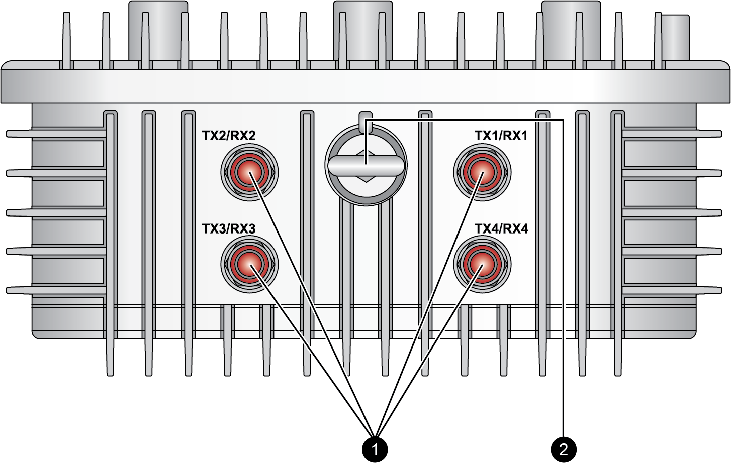
The PA-455R-5G firewall features serviceable
components on the top and bottom panels.
The following image shows the top panel of the PA-455R-5G and the
table describes each top panel component.
| Item | Component | Description |
|---|---|---|
|
1
|
Antenna connectors
|
Four connectors to install 4x4 MIMO antennas that provide 5G
connectivity to the device. The firewall does not ship with
antennas.
|
|
2
|
Lifting eyebolt
|
An eyebolt that is used for lifting or carrying the firewall during
installation.
The eyebolt is not intended
to be used as a mount or attachment to a fixed structure. |
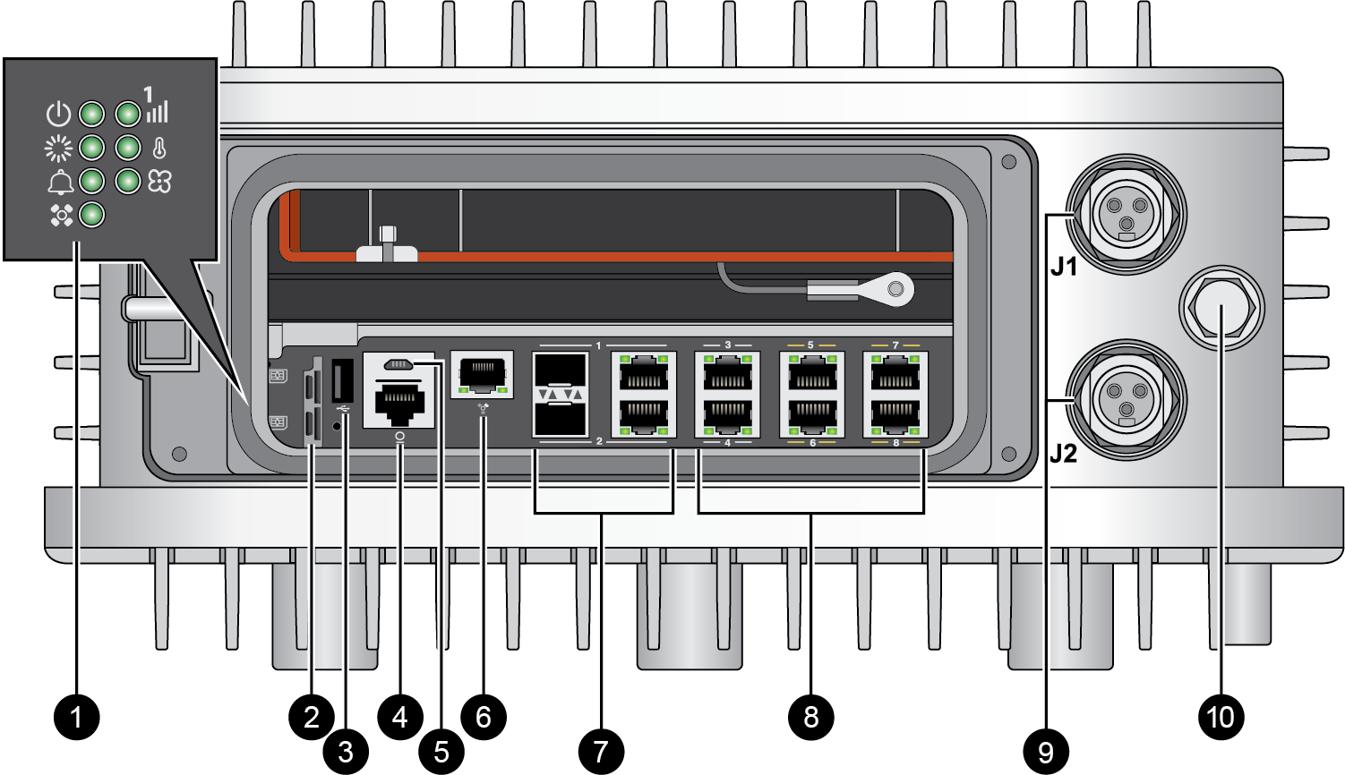
The following image shows the bottom panel of the
PA-455R-5G after the cover and caps have been removed. The table describes each bottom
panel component.
| Item | Component | Description |
|---|---|---|
|
1
|
LED status indicators
|
Seven LEDs that indicate the status of the firewall hardware
components (see Interpret the LEDs on a PA-400R Series Firewall).
|
|
2
|
SIM slots
|
Once the cover is removed, there are two slots in which you can
install 4FF SIM cards to enable mobile network connectivity. The
SIMs support 1.8v.
|
|
3
| USB slot |
USB port for debugging and administration only. Use this port to
bootstrap the firewall.
Bootstrapping enables you to provision the firewall with a specific
PAN-OS configuration and then license it and make it operational on
your network.
|
|
4
|
CONSOLE port
(RJ-45)
|
Use this port to connect a management computer to the firewall using
a RJ-45 to USB cable and terminal emulation software.
The console connection provides access to firewall boot messages, the
Maintenance Recovery Tool (MRT), and the command line interface
(CLI).
Use the following settings to configure your terminal emulation
software to connect to the console port:
|
|
5
|
CONSOLE port
(Micro USB)
|
Use this port to connect a management computer to the firewall using
a standard Type-A USB-to-micro USB cable (not included with the
firewall).
The console connection provides access to firewall boot messages, the
Maintenance Recovery Tool (MRT), and the command line interface
(CLI).
Refer to Micro USB Console Port for
more information and to download the Windows driver or to learn how
to connect from a Mac or Linux computer.
|
|
6
|
Management port
|
Use this Ethernet 1Gbps port to access the management web interface
and perform administrative tasks. The firewall also uses this port
for management services, such as retrieving licenses and updating
threat and application signatures.
|
|
7
|
SFP/RJ-45 combo ports
|
Two SFP/RJ-45 combo ports for 10/100/1000Mbps speeds.
|
|
8
|
RJ-45 ports
|
Six RJ-45 10/100/1000Mbps ports for network traffic.
You can set the link speed and duplex mode or choose
auto-negotiate.
Ports 5, 6, 7, and 8 are Power over Ethernet (PoE) ports. They can be
configured to transfer power to a connected device.
|
|
9
|
AC power inputs
|
Use the AC power inputs to connect power to the firewall. Both power
inputs must be connected to a power source for the firewall to
operate.
(Not pictured) Ground points are located on the side of the
device.
|
|
10
|
Breather valve
|
A breather valve that prevents the buildup of pressure and
condensation in the sealed enclosure.
|