PA-400R Series Front Panel
Table of Contents
PA-400R Series Front Panel
Learn about the PA-400R Series firewall front-panel components.
View the front panel components of your PA-400R Series firewall.
To review the specifications of supported Palo Alto Networks®
interfaces and transceivers, refer to the datasheet.
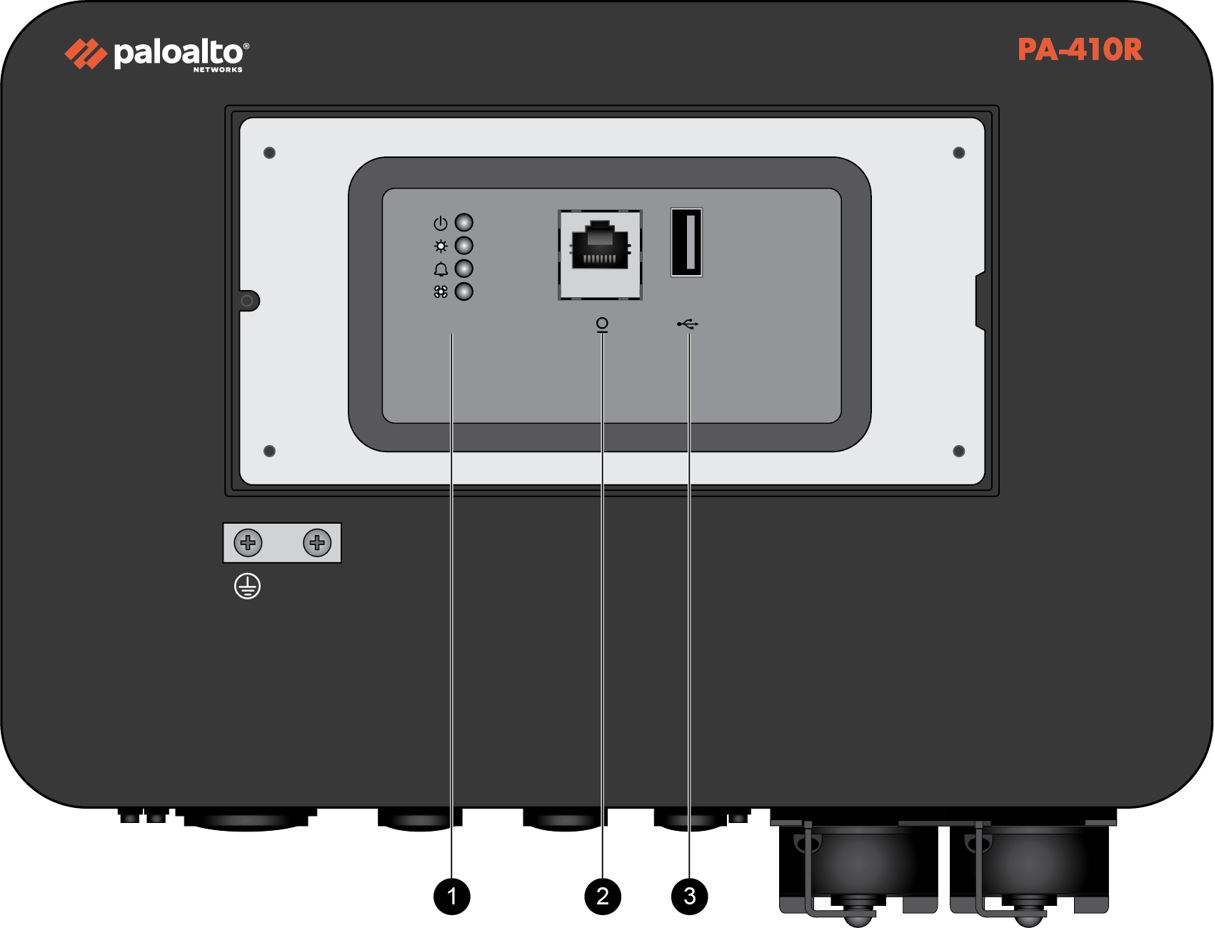
The front
panels of the PA-410R and PA-410R-5G are similar except that the PA-410R-5G features
antennas and has an additional LED to denote cellular status. The following
image shows the front panel of the PA-410R with its cover removed. The table describes
each front panel component.
| Item | Component | Description |
|---|---|---|
|
1
|
LED status indicators
|
LEDs that indicate the status of the firewall hardware components
(see Interpret the LEDs on a PA-400R Series Firewall).
The PA-410R has four LEDs and the PA-410R-5G
has five LEDs.
|
|
2
|
CONSOLE port
|
Use this port to connect a management computer to the firewall using
a RJ-45 to USB cable and terminal emulation software.
The console connection provides access to firewall boot messages, the
Maintenance Recovery Tool (MRT), and the command line interface
(CLI).
Use the following settings to configure your terminal emulation
software to connect to the console port:
|
|
3
|
USB port
|
Use this USB port to bootstrap the firewall.
Bootstrapping enables you to provision the firewall with a specific
PAN-OS configuration and then license it and make it operational on
your network.
|
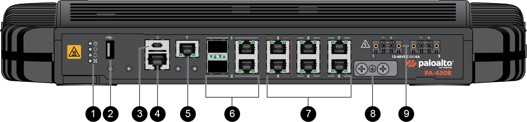
The following image shows the front panel of the PA-450R
and the table describes each front panel component.
| Item | Component | Description |
|---|---|---|
|
1
|
LED status indicators
|
Four LEDs that indicate the status of the firewall hardware
components (see Interpret the LEDs on a PA-400R Series Firewall).
|
|
2
|
USB port
|
Use this port to bootstrap the firewall.
Bootstrapping enables you to provision the firewall with a specific
PAN-OS configuration and then license it and make it operational on
your network.
|
|
3
|
CONSOLE port
(Micro USB)
|
Use this port to connect a management computer to the firewall using
a standard Type-A USB-to-micro USB cable (not included with the
firewall).
The console connection provides access to firewall boot messages, the
Maintenance Recovery Tool (MRT), and the command line interface
(CLI).
Refer to Micro USB Console Port for
more information and to download the Windows driver or to learn how
to connect from a Mac or Linux computer.
|
|
4
|
CONSOLE port
(RJ-45)
|
Use this port to connect a management computer to the firewall using
a RJ-45 to USB cable and terminal emulation software.
The console connection provides access to firewall boot messages, the
Maintenance Recovery Tool (MRT), and the command line interface
(CLI).
Use the following settings to configure your terminal emulation
software to connect to the console port:
|
|
5
|
Management port
|
Use this Ethernet 1Gbps port to access the management web interface
and perform administrative tasks. The firewall also uses this port
for management services, such as retrieving licenses and updating
threat and application signatures.
|
|
6
|
SFP/RJ-45 combo ports
|
Two SFP/RJ-45 combo ports for 10/100/1000Mbps speeds.
|
|
7
|
RJ-45 ports
|
Six RJ-45 10/100/1000Mbps ports for network traffic.
Ports 3 and 4 are fail-open ports. They can be configured to provide
a pass-through connection despite power or operating system
failure.
|
|
8
|
Ground studs
|
Use a dual screw ground lug to connect the firewall to earth ground
(ground cable not included).
|
|
9
|
DC power inputs
|
Use the DC power inputs to connect power to the firewall. A second
power supply can be used for redundancy.
|
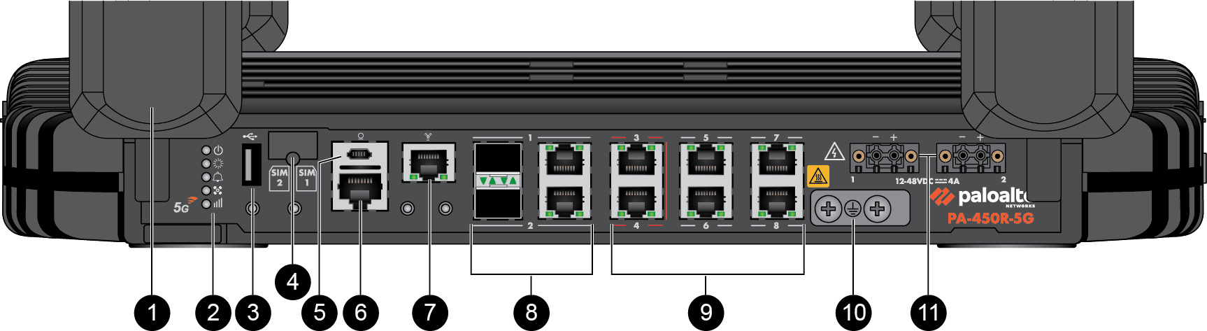
The following image shows the front
panel of the PA-450R-5G and the table describes each front panel component.
| Item | Component | Description |
|---|---|---|
|
1
|
Antennas
|
Four antennas that provide 5G connectivity to the device. The
firewall does not ship with the antennas installed.
|
|
2
|
LED status indicators
|
Five LEDs that indicate the status of the firewall hardware
components (see Interpret the LEDs on a PA-400R Series Firewall).
|
|
3
|
USB port
|
Use this port to bootstrap the firewall.
Bootstrapping enables you to provision the firewall with a specific
PAN-OS configuration and then license it and make it operational on
your network.
|
|
4
|
SIM slot
|
Install up to two nano SIMs into this slot to enable mobile network
connectivity.
The SIM cards must be rated to 85C. |
|
5
|
CONSOLE port
(Micro USB)
|
Use this port to connect a management computer to the firewall using
a standard Type-A USB-to-micro USB cable (not included with the
firewall).
The console connection provides access to firewall boot messages, the
Maintenance Recovery Tool (MRT), and the command line interface
(CLI).
Refer to Micro USB Console Port for
more information and to download the Windows driver or to learn how
to connect from a Mac or Linux computer.
|
|
6
|
CONSOLE port
(RJ-45)
|
Use this port to connect a management computer to the firewall using
a RJ-45 to USB cable and terminal emulation software.
The console connection provides access to firewall boot messages, the
Maintenance Recovery Tool (MRT), and the command line interface
(CLI).
Use the following settings to configure your terminal emulation
software to connect to the console port:
|
|
7
|
Management port
|
Use this Ethernet 1Gbps port to access the management web interface
and perform administrative tasks. The firewall also uses this port
for management services, such as retrieving licenses and updating
threat and application signatures.
|
|
8
|
SFP/RJ-45 combo ports
|
Two SFP/RJ-45 combo ports for 10/100/1000Mbps speeds.
|
|
9
|
RJ-45 ports
|
Six RJ-45 10/100/1000Mbps ports for network traffic.
You can set the link speed and duplex mode or choose
auto-negotiate.
Ports 3 and 4 are fail-open ports. They can be configured to provide
a pass-through connection despite power or operating system
failure.
|
|
10
|
Ground studs
|
Use a dual screw ground lug to connect the firewall to earth ground
(ground cable not included).
|
|
11
|
DC power inputs
|
Use the DC power inputs to connect power to the firewall. A second
power supply can be used for redundancy.
|
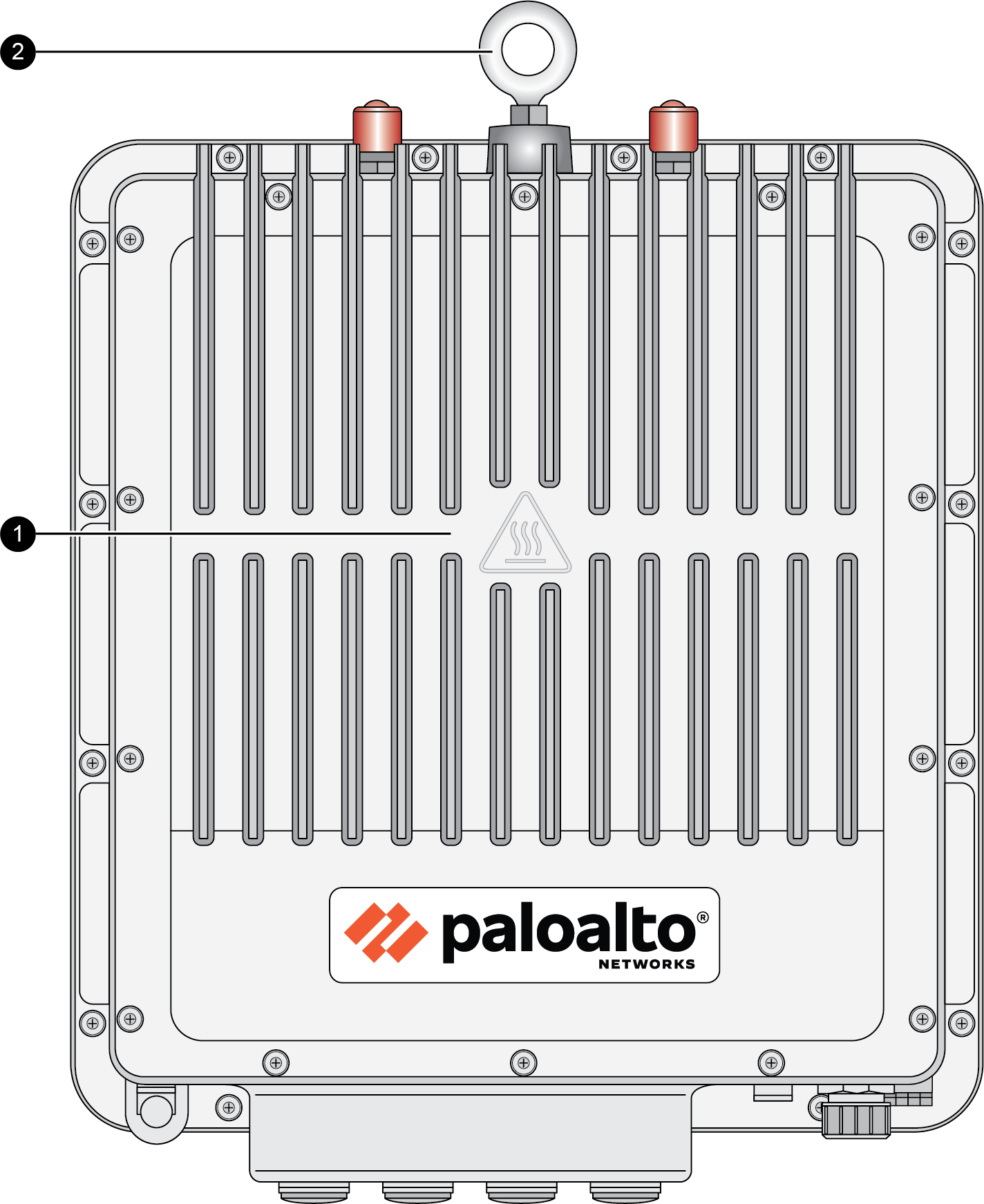
The following image shows the front
panel of the PA-455R-5G and the table describes each front panel component.
| Item | Component | Description |
|---|---|---|
|
1
|
Front cover heat sink
|
A heat sink cover that helps to dissipate heat from the firewall.
The heat sink cover should
not be removed at any point. |
|
2
|
Lifting eyebolt
|
An eyebolt that is used for lifting or carrying the firewall during
installation.
The eyebolt is not intended
to be used as a mount or attachment to a fixed structure. |