PA-5400 Series Front Panel
Table of Contents
PA-5400 Series Front Panel
Learn about the components located on the front of the
PA-5400 Series firewall.
The following image shows the front panel of the PA-5410, PA-5420, PA-5430, PA-5440, and PA-5445 firewalls. The table describes each front panel
component.
To review the specifications of supported Palo Alto Networks®
interfaces and transceivers, refer to the datasheet.
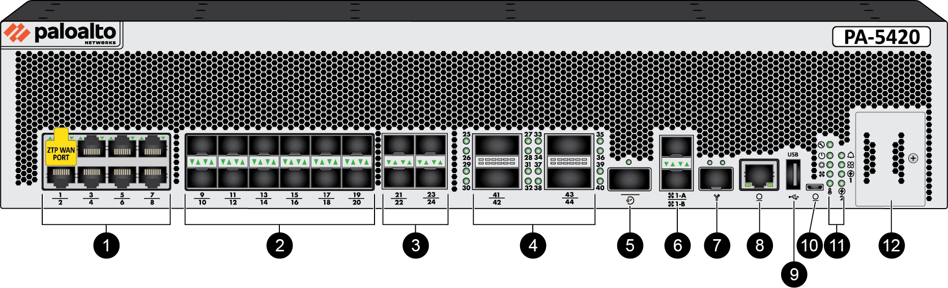
Item | Component | Description |
|---|---|---|
1 | Ethernet ports 1 through 8 | Eight RJ-45 10Mbps/100Mbps/1Gbps/2.5Gbps/5Gbps/10Gbps
ports for network traffic.
Port 1 is a Zero Touch Provisioning (ZTP) port. The ZTP port can be
used to automate the on-boarding of new firewalls to a Panorama
management server. To use the ZTP port, read how to boot the firewall in ZTP
mode. |
2 | SFP+ ports 9 through 20 | Ports 9 through 20 are SFP (1Gbps) or SFP+ (10Gbps)
based on the installed transceiver. The SFP ports can
be remapped as HA-1 ports via PAN-OS or Panorama. These remapped
HA-1 ports offer high availability connectivity over a longer distance
than what is permitted by the HA1-A and HA1-B ports listed below. |
3 | SFP28 ports 21 through 24 | Four SFP28 (25Gbps) ports that also support 1Gbps/SFP and 10Gbps/SFP+ modules. The FEC setting of the remote endpoint
must be set to RS-FEC to ensure that the link remains up. |
4 | QSFP28 ports 25 through 44 | Four form-factor pluggable (QSFP+/QSFP28) 40Gbps/100Gbps Ethernet ports. Each interface supports
breakout mode to create four 10Gbps or four 25Gbps ports each.
Refer to Interpret the PA-5400 Series LEDs to view the LED
behavior of these ports.
Setting the interface speed to
auto defaults the ports to breakout mode.
Manually setting the interface speed allows you to use each
individual port. |
5 | HSCI port | One 40Gbps port that can be used to connect
two PA-5400 Series firewalls in a high availability (HA) configuration
as follows:
The
HSCI ports must be connected directly between the two firewalls
in the HA configuration (without a switch or router between them).
When directly connecting the HSCI ports between two PA-5400 Series
firewalls that are physically located near each other, Palo Alto Networks
recommends that you use an active or passive QSFP+ cable. For
installations where the two firewalls are not near each other and
you cannot use an active or passive QSFP+ cable, use a standard
QSFP+ transceiver and the appropriate cable length. |
| 6 | HA1-A and HA1-B ports | Two SFP+ 1Gbps/10Gbps ports for high availability (HA)
control. If the firewall dataplane restarts due to a
failure or manual restart, the HA1-B link will also restart. If
this occurs and the HA1-A link is not connected and configured,
then a split brain condition occurs. Therefore, we recommend that
you connect and configure the HA1-A ports and the HA1-B ports to
provide redundancy and to avoid split brain issues. |
| 7 | MGT port | Use this SFP+ 1Gbps/10Gbps port to access
the management web interface and perform administrative tasks. The
firewall also uses this port for management services, such as retrieving
licenses and updating threat and application signatures.
The management port supports copper and fiber SFP/SFP+
transceivers for 1G connectivity. For 10G connectivity, the
management port only supports fiber SFP/SFP+ transceivers. The Management port cannot be
used to configure HA1 or HA1 backup. You must use the dedicated
HA1-A and HA1-B ports. |
| 8 | CONSOLE port (RJ-45) | Use this port to connect a management computer
to the firewall using a 9-pin serial-to-RJ-45 cable and terminal emulation
software. The console connection provides access to firewall boot
messages, the Maintenance Recovery Tool (MRT), and the command line
interface (CLI). If your management computer does not
have a serial port, use a USB-to-serial converter. Use
the following settings to configure your terminal emulation software
to connect to the console port:
|
| 9 | USB port | A USB port that accepts a USB flash drive
with a bootstrap bundle (PAN-OS configuration). Bootstrapping
speeds up the process of configuring and licensing the firewall
to make it operational on the network with or without internet access. |
| 10 | CONSOLE port (Micro USB) | Use this port to connect a management computer
to the firewall using a standard Type-A USB-to-micro USB cable. The
console connection provides access to firewall boot messages, the
Maintenance Recovery Tool (MRT), and the command line interface
(CLI). Refer to the Micro USB Console Port page for more
information and to download the Windows driver or to learn how to
connect from a Mac or Linux computer. |
| 11 | LED status indicators | Eight LEDs that indicate the status of the
firewall hardware components (see Interpret the PA-5400 Series LEDs). |
| 12 | System Drive Module | Secures the device SSDs. |