PA-5400 MPC-A Component Descriptions
Table of Contents
PA-5400 MPC-A Component Descriptions
Learn about the PA-5400 MPC-A components and their respective
functions.
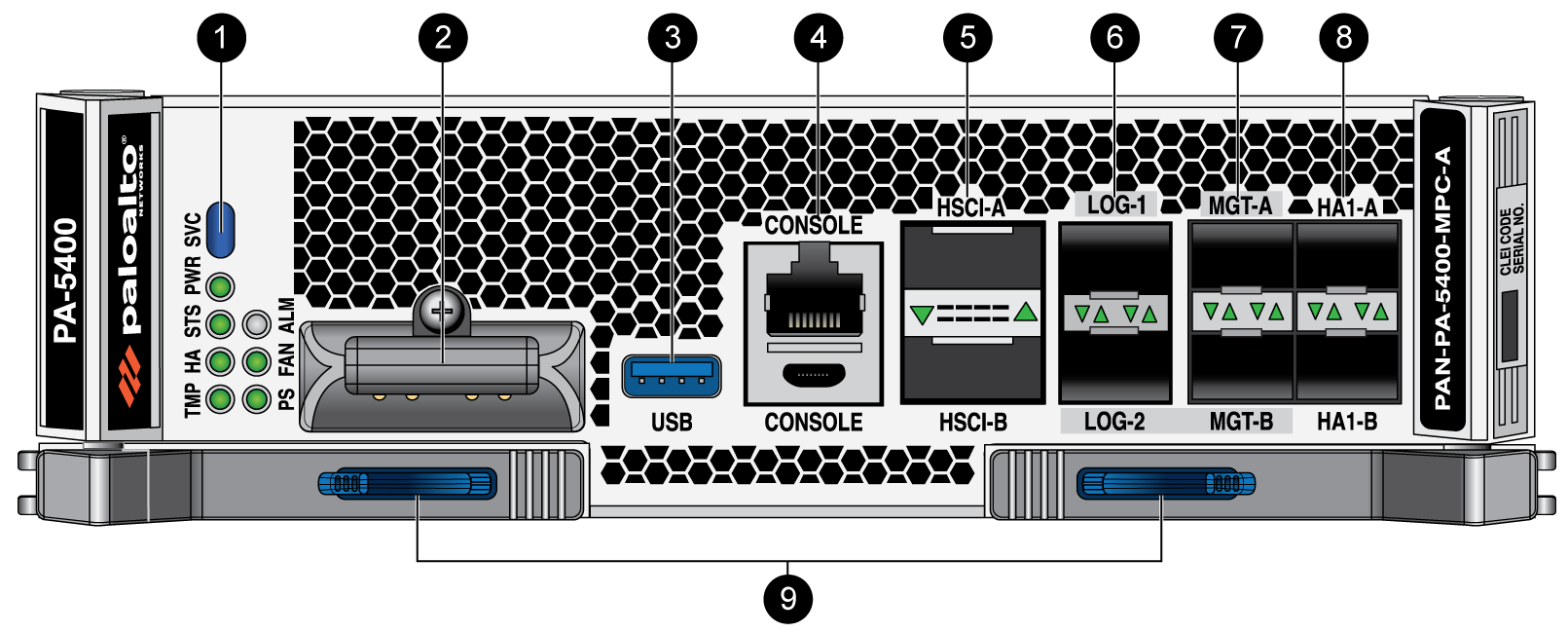
The following image shows the PA-5400
MPC-A and the table below describes each labeled component.
To review the specifications of supported Palo Alto Networks®
interfaces and transceivers, refer to the datasheet.
Item | Component | Description |
|---|---|---|
1 | LED Indicators | Eight LEDs that indicate the status of various hardware
components. For details on the LEDs, see Interpret the PA-5400 MPC-A LEDs |
2 | Logging Drive Cover | Secures the logging drive in the MPC. By
default, the MPC does not have a logging drive installed. For information about
installing a logging drive, see Install an MPC Logging Drive. |
3 | USB Port | One USB port that accepts a USB flash drive
that contains a bootstrap bundle (PAN-OS configuration) that enables
you to bootstrap the firewall. Bootstrapping enables you to provision
the firewall with a specific configuration, license it, and make
it operational on the network. |
4 | RJ-45 Console Port and Micro USB Console Port | RJ-45 Console Port Use the
console port to connect a management computer to the firewall using
a 9-pin serial-to-RJ-45 cable and terminal emulation software. Micro
USB Console Port Use the console port to connect a management computer
to the firewall using a standard Type-A USB-to-micro USB cable and
terminal emulation software. The console connection provides
access to firewall boot messages, the Maintenance Recovery Tool
(MRT), and the command line interface (CLI). If your
management computer does not have a serial port, use a USB-to-serial converter. |
5 | HSCI-A and HSCI-B (High Speed Chassis Interconnect)
Ports | Quad-SFP+ (QSFP+/QSFP28) interfaces used
to connect two PA-5400 Series firewalls for a high availability (HA)
configuration. Each port offers 80GE (two 40Gbps links) or 200GE
(two 100Gbps links) connectivity and is used for HA2 data link in
an active/passive configuration. When in active/active mode, the
port is also used for HA3 packet forwarding for asymmetrically routed
sessions that require Layer 7 inspection for App-ID™ and Content‑ID™. In
a typical installation, HSCI-A on the first firewall connects directly
to HSCI-A on the second firewall and HSCI-B on the first firewall
connects to HSCI-B on the second firewall. The purpose of HSCI-B
is to increase the bandwidth for HA2/HA3 processing. This provides
full 80-200Gbps transfer rates. In software, both ports (HSCI-A and
HSCI-B) are treated as one HA interface. The HSCI ports are
not routable and must be connected directly to each other, not through
a switch. Palo Alto Networks recommends using an active or passive QSFP+
cable to connect the two HSCI ports. You can configure HA2 (data link) on the HSCI ports or on NC data ports. When configuring on
dataplane ports, you must ensure that both the HA2 and
HA2-Backup links are configured on dataplane interfaces.
HA2-Backup cannot be configured on the HSCI ports. For installations where the two firewalls
are not near each other and you cannot use an active or passive
QSFP+ cable, use a standard QSFP+ transceiver and the appropriate
cable length. |
6 | Logging Ports | Two SFP/SFP+ logging ports that offer 1/10GE connectivity and are used as log interfaces. LOG-1
and LOG-2 are bundled as a single logical interface called
bond1. Bond1 uses LACP (link
aggregation control protocol) as IEEE 802.3ad. Set the
Mode for LACP status queries to
Active and the
Transmission Rate for LACP query and
response exchanges to Slow. You
must Configure Log Forwarding to
forward logs from the log interface to one or more log collectors.
If the log interface is not configured, the management interface
is used to forward logs instead. LOG-1
and LOG-2 only support fiber SFP/SFP+ transceivers. Copper SFP/SFP+
transceivers are not supported. |
7 | Management Ports | Two SFP/SFP+ management ports providing 1/10GE connectivity that are used to access the
management interface. MGT-A (active) and MGT-B (backup) are
bundled as a single logical interface called
bond0. The two bonded ports provide
redundancy, which enables the management interface to remain
active if one interface goes down. LACP is not enabled on
Bond0.
The management interface is used for log forwarding by default if
you have not configured a log interface.
The Management ports
cannot be used to configure HA1 or HA1 backup. You must use the
dedicated HA1-A and HA1-B ports. When using bond0 with a switch, the switch should be configured with either a dynamic LAG setting
or no LAG setting. Configuring the switch to use a static
LAG setting causes the switch to lose connectivity. To
manage the firewall, change your management computer IP address
to 192.168.1.2, connect an SFP+ cable from your computer to one
of the MGT ports and browse to https:// 192.168.1.1. The default
login name is admin and the default password is admin.
MGT-A and MGT-B support copper and fiber SFP/SFP+
transceivers for 1G connectivity. For 10G connectivity,
MGT-A and MGT-B only support fiber SFP/SFP+ transceivers.
|
8 | HA1 Ports | Two SFP/SFP+ ports providing 1/10GE connectivity for
high availability (HA) control and synchronization. Connect this
port directly from the HA1-A port on the first firewall in an HA
pair to the HA1-A port on the second firewall in the pair, or connect
these two ports to each other through a switch or router. The
HA1-B port, when connected to the HA1-B port on a second firewall,
is used for a backup connection. View the HA Ports on Palo Alto Networks
Firewalls for more information. |