Replace a PA-5400 Series Fan Assembly
Table of Contents
Replace a PA-5400 Series Fan Assembly
Learn how to replace a failed fan assembly in the PA-5410, PA-5420, PA-5430, PA-5440, and PA-5445 firewalls.
The PA-5410, PA-5420, PA-5430, PA-5440, and PA-5445 have three
dual-rotor, single fan assemblies on its rear side. Each single fan assembly can be
individually removed and replaced. When all fans are functioning as expected, the
fan LED glows green. If a fan fails, the fan LED glows red. If this occurs, replace
the faulty fan assembly immediately to avoid service interruption.
You can replace a failed fan assembly while the firewall is powered on; however, there is a time
limit of 15 seconds starting when the fan assembly is removed to replace it
before the thermal protection circuit automatically powers down the
firewall.
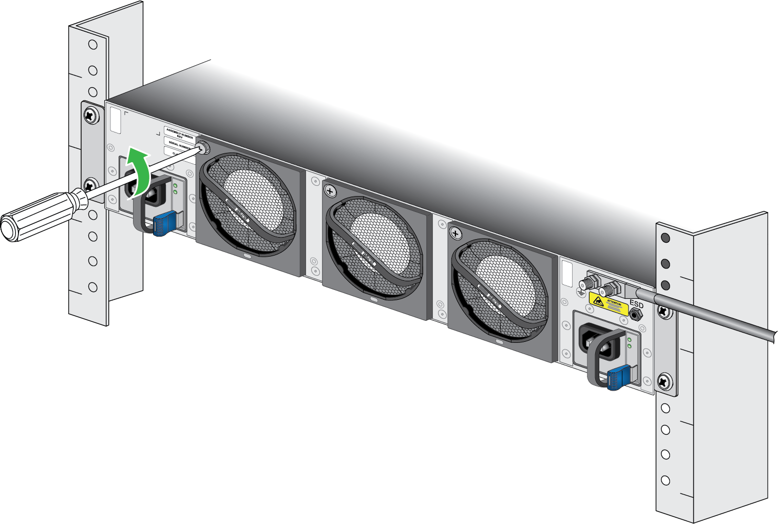
- Put the provided ESD wrist strap on your wrist ensuring that the metal contact is touching your skin. Then attach (snap) one end of the ground cable to the wrist strap and remove the alligator clip from the banana clip on the other end of the ESD grounding cable. Plug the banana clip end into the ESD port located on the rear of the appliance before handling ESD sensitive hardware. For details on the ESD port location, see PA-5400 Series Back Panel.When removing a fan assembly, first pull the fan assembly out about 1 inch (2.5cm) and wait 10 seconds. This allows enough time for the working fans to stop spinning.Remove the replacement fan assembly from the packaging and have it ready.Identify the failed fan assembly by checking the fault LEDs of each fan. In the event of a failure, the LED on the fan assembly will be red.Loosen the captive screw holding the fan assembly in place.
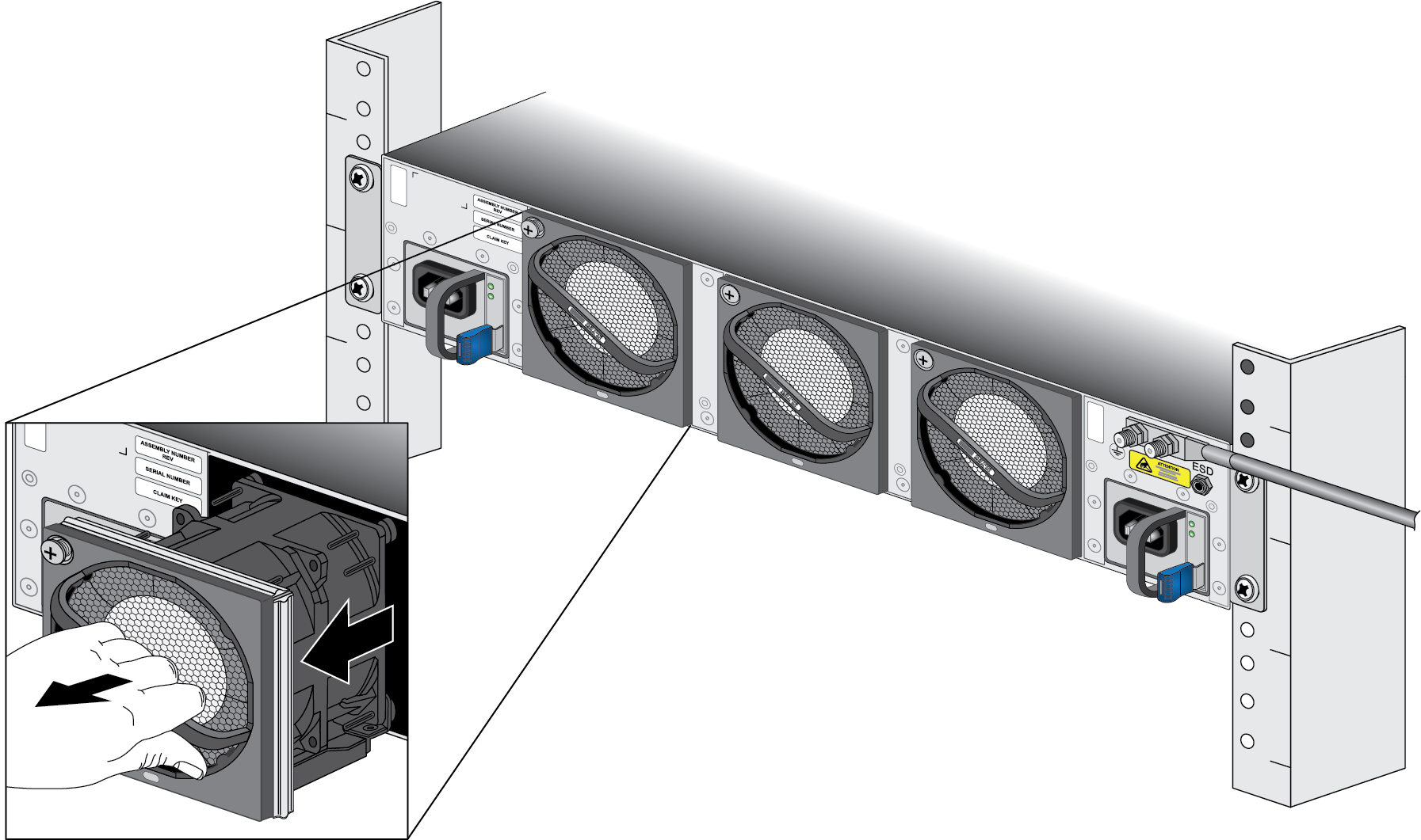
![]() While gripping the fan assembly handle, gently pull the fan assembly out of its slot.
While gripping the fan assembly handle, gently pull the fan assembly out of its slot.![]() Install the replacement fan by sliding it into the vacant fan slot. Tighten the captive screw by turning it clockwise until it is secure. Ensure that the fan assembly is secure by gently pulling on the handle.Verify that the new fan assembly is operational by noting the status of the fan LED on the front panel. You can also view the status of the fan trays by entering the following command:
Install the replacement fan by sliding it into the vacant fan slot. Tighten the captive screw by turning it clockwise until it is secure. Ensure that the fan assembly is secure by gently pulling on the handle.Verify that the new fan assembly is operational by noting the status of the fan LED on the front panel. You can also view the status of the fan trays by entering the following command:admin@PA-5420> show system environmentals fan-trayTo view the status of each fan on a fan assembly, run the following command:admin@PA-5420> show system environmentals fans