Configure an NGFW Cluster
Table of Contents
Configure an NGFW Cluster
Configure an NGFW cluster of two PA-7500 Series firewalls for node
redundancy.
| Where Can I Use This? | What Do I Need? |
|---|---|
|
One of the following:
|
Before you configure an NGFW cluster, perform the following prerequisites:
- Confirm that Panorama and the PA-7500 Series firewalls that you will assign to an NGFW cluster are all running the same software version (PAN-OS 11.1.3 or a later 11.1 release).
- Install Panorama Clustering plugin 2.0.0 if you're using PAN-OS 11.1.3; refer to Install Panorama Plugins. For subsequent PAN-OS releases, you must install a compatible Panorama Clustering plugin release. Also refer to the Panorama plugin for Clustering in the VM-Series and Panorama Plugin Release Notes.
- Be familiar with Panorama tasks, such as managing devices and creating templates, template stacks, and device groups.
- Add the two PA-7500 Series firewalls as managed devices of Panorama so that they are communicating with each other over the management interface. Confirm by selecting , and verify the two firewalls (nodes) have an IP address on their management interface and the Device State is Connected.
- Connect the PA-7500 Series firewalls back-to-back with 100G or 400G HSCI-A and HSCI-B links. (Verify the connections on each firewall by using the CLI command show interface all to see the hsci-a and hsci-b interfaces.)
- Familiarize yourself with NGFW Clusters.
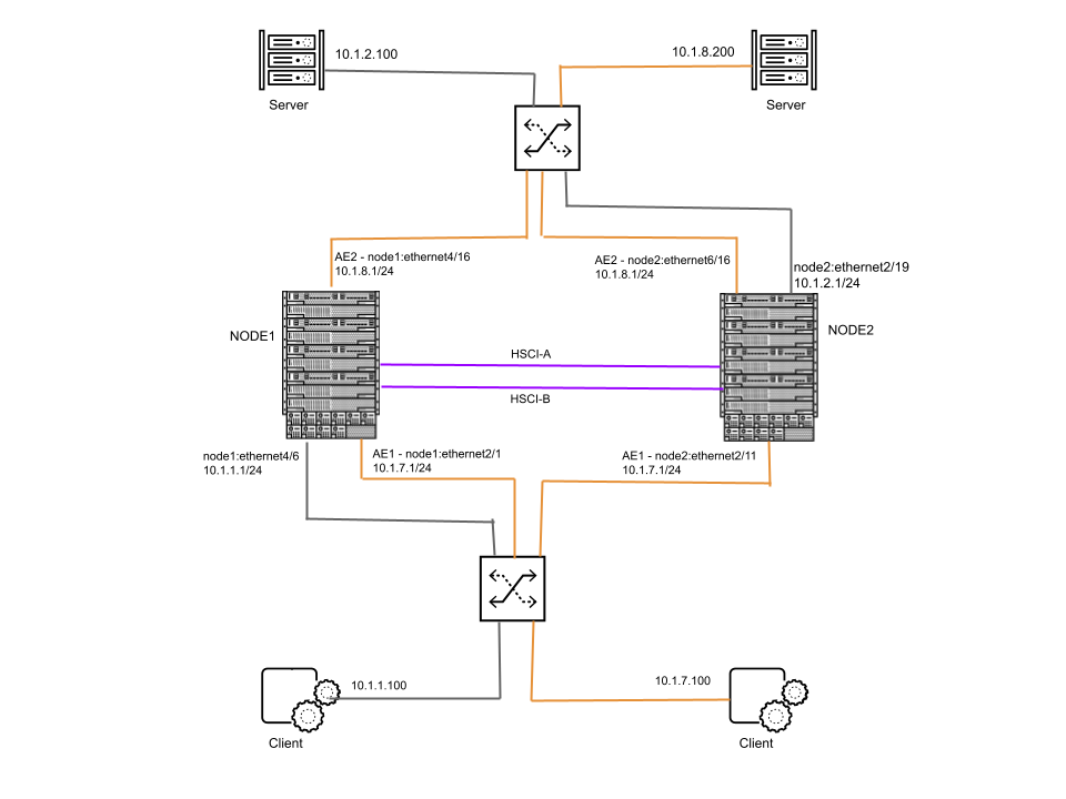
The steps in the example task to configure an NGFW cluster are based on this topology
example of two MC-LAGs. The orange links connected to Node 1 and Node 2 on the
client side belong to AE1 (an MC-LAG). The orange links connected to Node 1 and Node
2 on the server side belong to AE2 (another MC-LAG). Traffic from the client at
10.1.7.100 goes to the switch and is then divided between the two ingress AE1
interfaces and then egresses the two AE2 interfaces to the switch, and then goes
over the orange link to the server at 10.1.8.200.
The gray links connected Node 1 and Node 2 are orphan ports. Traffic from the client
at 10.1.1.100 goes to the switch, to Node 1, across an HSCI interface to Node 2,
egresses Node 2 to the switch, and then to the server at 10.1.2.100.
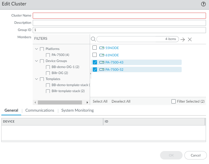
- Create an NGFW cluster.
- Select .
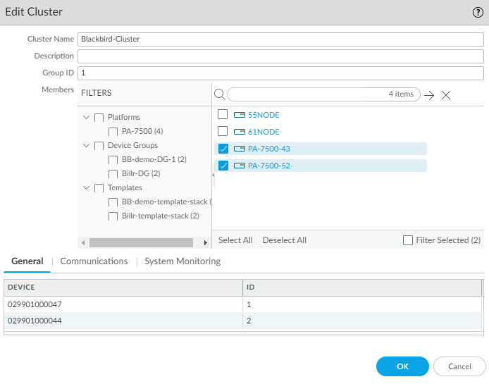
- Enter a Cluster Name containing zero or more alphanumeric characters, underscores (_), hyphens (-), dots (.), or spaces.
- Select Cluster Type as PA.
- Click OK.
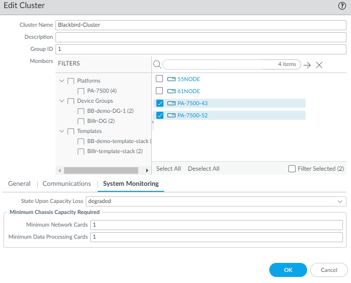
- Add the firewalls to the cluster.
- Select and select the cluster you created.
- Enter a Group ID in the range 1 to 63; the default is 1.
- Select the two PA-7500 Series firewalls to assign to the cluster. The first firewall you select automatically becomes Node 1.

- Click OK.
- View the firewalls in the cluster by selecting and selecting the cluster you created. The General tab displays nonconfigurable fields: Device serial number and Node ID (1 or 2). Click OK to close the window.
- Select Commit to Panorama and Commit. Both firewalls are rebooted and get assigned a Node ID, the existing configuration (policy, network, etc.) is cleared, and the firewalls are connected back to Panorama.
- Select Push to Devices, select Push All Changes, select the newly created firewall cluster, and Push.
- (Optional) Verify the cluster state and node state.
- > show cluster leader
- > show cluster local node-id
- > show cluster local state
- > show cluster all
- > exit
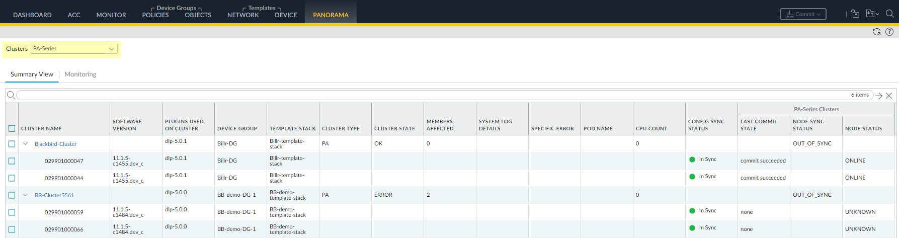
- View the Config Sync Status.
- Select and select PA-Series.
- View the Config Sync Status. After the Commit All is successful, the firewalls have a Config Sync Status of In Sync.
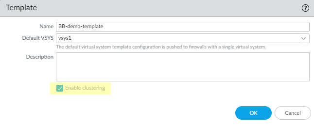
- Add a cluster template.
- Select and Add a template.
- Enter a Name and Description of the template.
- Enable clustering. You must enable clustering when you first create the template; you can't go back to enable clustering later.
- Click OK.
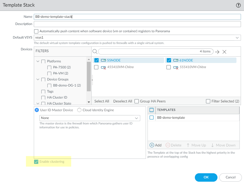
- Create a template stack.
- Select .
- Enter a Name for the template stack.
- In the Devices section, select the two firewalls in the cluster.
- In the Templates section, Add the template you created.
- Enable clustering. You must enable clustering when you first create the template stack; you can't go back to enable clustering later. (If you don't Enable clustering for the template stack now, it won't match the template and an Operation Failed message appears.)
- Click OK.
- Add a device group.
- Select .
- Enter a Name for the device group.
- In the Devices section, select the Names of the two firewalls in the cluster.
- In the Reference Templates section, Add the template stack that you created.
- Click OK.
- Commit to Panorama and Commit to apply your configuration in Panorama.
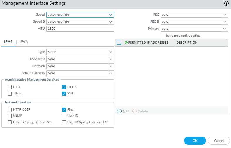
- (Two-node cluster only) Verify that the management interface permits the same IP addresses on the two nodes. The firewalls use the management interface to exchange heartbeats to detect and avoid a split-brain situation.
- Select .
- In the Template field, select your template.
- Select the Management interface.
- If you added Permitted IP Addresses on one of the nodes, you must also permit the same IP addresses on the peer node. Each node must be able to reach the management interface of the peer node. (If you deny the IP address or network of the peer, split brain detection won't work.)
- Click OK.
- Configure the template.
- Select
- In the Template field, select your template.
- To configure the orphan port, configure a Layer 3 interface on the firewall that connects to the client.
- Select and Add Interface.
- Select the Node ID (1 for this example).
- Select the Slot (Slot 4).
- Select the Interface Name, for example, node1:ethernet4/6.
- Select the Interface Type as Layer3.
- On the Config tab, create a Logical Router by adding a Name; click OK.
- Create a Security Zone, such as client.
- Select IPv4, select the Type as Static, for example, and Add the IPv4 address with netmask (10.1.1.1/24 in this example).Alternatively, select IPv6, Enable IPv6 on the interface, select the Type as Static, and Add the IPv6 Address with network prefix length. This task example uses static IP addressing; NGFW clustering also supports DHCP, DHCPv6, PPPoE, and PPPoEv6.
- Select the Advanced tab and then the Other Info tab.
- For Management Profile, create a new Interface Management profile to allow access to the interface. Select the management and network services allowed (such as HTTPS, SSH, and Ping) and click OK.
- Click OK.
- Configure the other orphan port on node 2, Slot 2, node2:ethernet2/19, using IP address 10.1.2.1/24 for the interface that faces the server. Create a different security zone. The gray path in the example topology is configured.
- Configure the AE interface (MC-LAG) for the client-facing interface on Node 1.
- Select and Add Aggregate Group.
- For Interface Name, next to ae, enter the interface number (in this example, 1).
- Select Interface Type as Layer3.
- On the Config tab, select the same Logical Router.
- Select the Security Zone.
- Click OK.
- Select IPv4, select the Type as Static, and Add the IPv4 address with netmask (10.1.7.1/24 in this example).
- (Optional) Configure LACP settings if you want to enable LACP for the aggregate group.
- Select the Advanced tab and then the Other Info tab.
- For Management Profile, create a new Interface Management profile to allow access to the interface. Select the services allowed and click OK.
- Click OK.
- Configure the AE interface (MC-LAG) for the server-facing interface for Node 1. For this interface, follow similar substeps as in the prior step, but configure AE2, add the IP address (10.1.8.1/24), the same logical router, and a server Security zone.
- Add an interface member to the MC-LAG on the client side.
- Select and Add Interface.
- On the Cluster Ethernet Interface, select the Node ID Node 1.
- Select the Slot (Slot 2).
- Select the Interface Name, for example, node1:ethernet2/1.
- Select the Interface Type as Aggregate Ethernet.
- Select the Aggregate Group, such as ae1.
- Click OK.
- Add a second interface member to the MC-LAG on the client side, assigning Node ID as Node 2, Slot 2, node2:ethernet2/11. Select the same Aggregate Group (ae1).
- Add an interface member to the MC-LAG on the server side. Select Node 1, Slot 4, node1:ethernet4/16. Select the Aggregate Group, ae2.
- Add a second interface member to the MC-LAG on the server side, assigning it to Node 2, Slot 6, node2:ethernet6/16. Select the Aggregate Group, such as ae2.
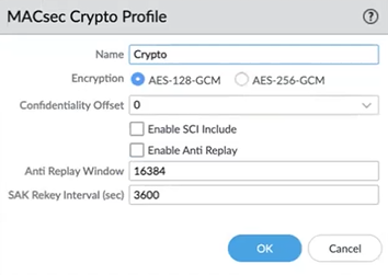
- (PAN-OS 11.1.5 and later releases) Prepare to configure MACsec for the HSCI ports by creating a MACsec profile.IMPORTANT: When you migrate from a non-MACsec cluster to a MACsec cluster, you must do so during a maintenance window.
- Select and select MACsec Policy.
- Add a MACsec crypto profile by Name, which contains zero or more alphanumeric characters, underscores (_), hyphens (-), or dots (.). The Name is a maximum of 31 characters.
- Select the Encryption type: AES-128-GCM (default) or AES-256-GCM.
- Select the Confidentiality Offset to specify a number of bytes (starting from the frame header), after which MACsec encrypts the bytes in a frame. Values are 0 (default), 30, or 50.
- Enable SCI Include to include the Secure Channel Identifier (SCI) tag in the Security Tag field of the MACsec header. The default is disabled.
- Enable Anti Replay to enable replay protection. This allows a MACsec port to accept frames out of order if they are within the Anti Replay Window. The default is disabled.
- Specify the Anti Replay Window size in the range 0 to 65,535; the default is 16,384. This value determines the range of packet numbers that the port will accept, for packets that might be out of order. The port will accept packets with a packet number greater than or equal to the last packet number minus the window size. For example, after the port receives packet number 12, if the window is 5, the port will subsequently accept only packets numbered 7 or higher.Specify an Anti Replay window size based on the traffic rate because the HSCI ports will likely experience packets arriving out of order due to prioritization or load balancing in the network.
- Specify the SAK Rekey Interval (sec) in seconds; range is 60 to 86,400; default is 3,600. Connectivity Association participants negotiate a Secure Association agreement, which includes a cipher suite and keys. A Key Server generates a Secure Association Key (SAK) from the Connectivity Association Key (CAK); the SAK is refreshed at the SAK rekey interval. The end-to-end nodes use the SAK to encrypt traffic for a given session. To avoid the SAKs of all interfaces being refreshed at the same time, MACsec might spread the rekeying actions evenly by subtracting a small random number from the SAK rekey interval.
- Click OK.
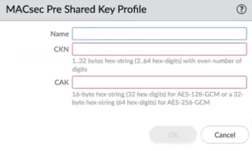
- (PAN-OS 11.1.5 and later releases) Create a MACsec Pre Shared Key Profile.
- Select and select Pre Shared Key.
- Add a MACsec Pre Shared Key Profile by Name, which contains zero or more alphanumeric characters, underscores (_), hyphens (-), dots (.), or spaces. The Name is a maximum of 31 characters.
- Enter the CKN (Connectivity Association Key Name) that identifies the Connectivity Association Key. The CKN is 1 byte to 32 bytes of hexadecimal string (2 to 64 hex digits) with an even number of digits; for example, 1234.
- Enter the CAK (Connectivity Association Key), which is a 16-byte hexadecimal string (32 hex digits) for AES-128-GCM, or a 32-byte hexadecimal string (64 hex digits) for AES-256-GCM. The CAK is used to generate all other keys used for MACsec. An example CAK for AES-128-GCM is 12345678912345678912345678912345. A CAK for AES-256-GCM is twice as long as a CAK for AES-128-GCM.The Pre Shared Key, CKN, and CAK must match on the two ends of the HSCI-A link. Likewise, the Pre Shared Key, CKN, and CAK must match on the two ends of the HSCI-B link.
- Click OK.
- (PAN-OS 11.1.5 and later releases) Commit to Panorama.
- (PAN-OS 11.1.5 and later releases) Push to Devices and Push Templates so that the devices have the MACsec profiles, thus allowing you to later push the cluster configuration with MACsec enabled.
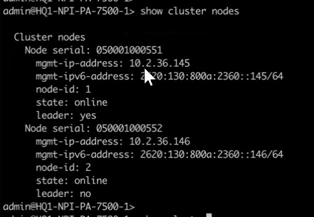
- (PAN-OS 11.1.5 and later releases) Identify the leader node and nonleader node.
- Access the CLI on one of the firewall nodes. (If you already know which node is the nonleader, access the CLI on the nonleader node.)
- >show cluster nodes
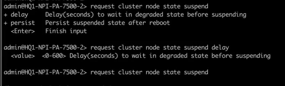
- (PAN-OS 11.1.5 and later releases) Suspend the nonleader node.
- Access the CLI on the nonleader node.
- >request cluster node state suspendThe suspension takes approximately 120 seconds (the default delay value).
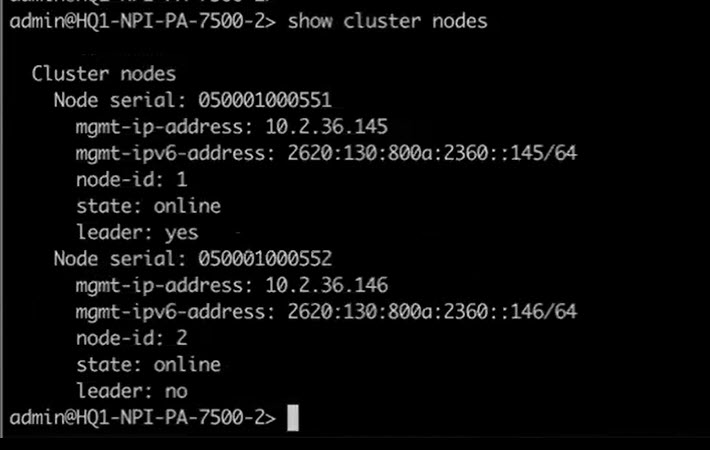
- (PAN-OS 11.1.5 and later releases) Confirm the nonleader node is suspended.
- >show cluster nodes
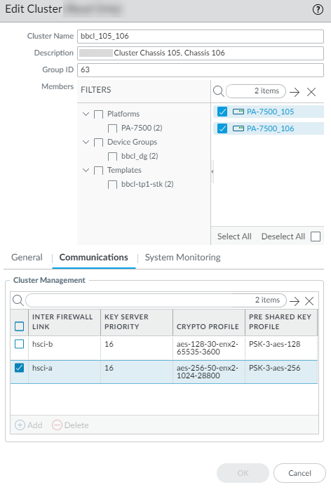
- (PAN-OS 11.1.5 and later releases) Apply your MACsec profiles to the HSCI-A and HSCI-B ports.
- Select and select Summary View.
- Select PA-Series or All Clusters.
- Select a Cluster Name to edit the cluster.
- Select Communications.
- Select hsci-a and enter the Key Server Priority in the range from 0 to 255; the default is 16. The lower the value, the higher the priority of the Key Server.If the priority values for the HSCI-A links on the two nodes are equal, the node with the lower MAC address is the Key Server. The Key Server (one of the nodes in the cluster) selects and advertises a cipher suite, and also generates the SAK from the CAK.
- For Crypto Profile, select the MACsec crypto profile you created or select the default profile.
- For Pre Shared Key Profile, select the profile you created.
- Select hsci-b and perform the same steps to assign a Key Server Priority and apply the crypto profile and pre-shared key Profile to the port.
- Click OK.
- (PAN-OS 11.1.5 and later releases) Commit, Commit to Panorama, and Commit.
- (PAN-OS 11.1.5 and later releases) Push to Devices and Push , which enables MACsec on the ports.
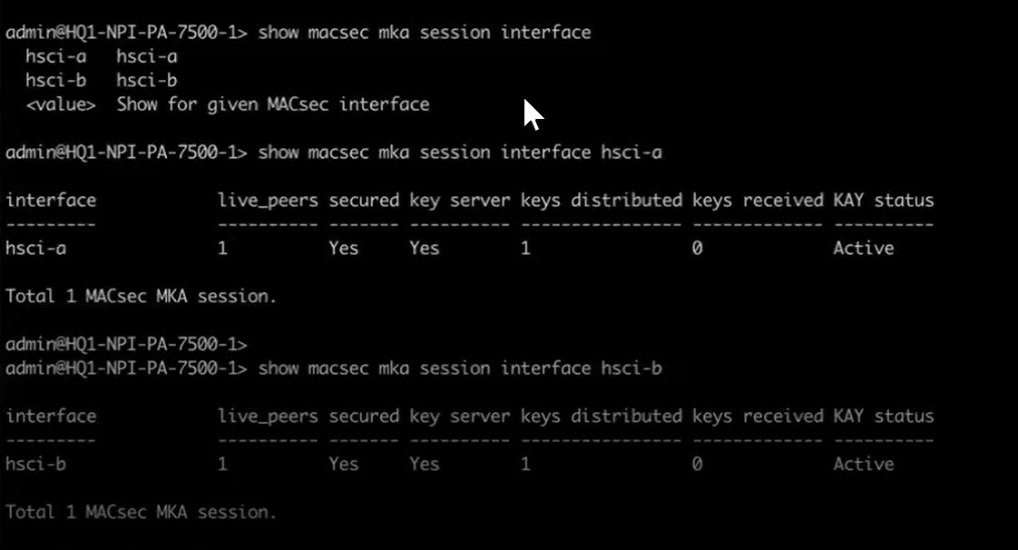
- (PAN-OS 11.1.5 and later releases) Confirm MACsec is enabled on both ports.
- >show macsec mka session interface hsci-a
- >show macsec mka session interface hsci-b
- (PAN-OS 11.1.5 and later releases) Unsuspend the nonleader node.
- Access the CLI on the nonleader node.
- >request cluster node state unsuspendIt takes a few minutes to unsuspend the nonleader node; the length of time depends on the traffic level.
- (PAN-OS 11.1.5 and later releases) Verify that both nodes are online.
- >show cluster nodes
- (PAN-OS 11.1.7 and later releases) (Optional) Enable multiple virtual systems for the firewalls in the template.
- Select and select the Template by name.
- For Mode, select Multi VSYS.
- Create Security policy rules.
- Select Policies and select the Device Group.
- Create Security policy rules to control access, such as allowing a specific source zone, destination zone, address, user, device, application, and service.
- Configure routing and other features your firewalls require (except for HA). Refer to the PAN-OS Administrator's Guide and the PAN-OS Networking Administrator's Guide.
- Configure system monitoring for the NGFW cluster.
- Select and select a cluster or a single firewall in the cluster.
- Select System Monitoring.
- Select the State Upon Capacity Loss:
- degraded—Specifies that the firewall will
be in a DEGRADED state if the count of functional network cards
or data processing cards goes below the configured Minimum
Network Cards or Minimum Data Processing Cards, respectively.
Furthermore:
- A cluster node in DEGRADED state has traffic ports down, but is still a part of the sharded (fragmented) member table.
- Data processing card resources of a DEGRADED cluster node can be used to process traffic and for Layer 7 processing.
- A cluster node in INIT or ONLINE state transitions to DEGRADED state when a soft fault is reported to the cluster node state machine.
- A cluster node in ONLINE state transitions to DEGRADED state (and a node in DEGRADED state remains in DEGRADED state) if you suspend the cluster node after a delay (using the CLI operational command: request cluster node state suspend). A delay allows data planes to gracefully complete Layer 7 processing or other processes that were underway.
- If all soft faults are cleared, the cluster node transitions to INIT state.
- If a hard fault occurs, a cluster node in DEGRADED state transitions to FAILED state.
- A cluster node in DEGRADED state transitions to SUSPENDED state if the maximum number of state flaps is seen or you suspend the cluster node.
- If a chassis has no functional data processing cards remaining (all DPC slots are powered off or in a FAILED state), the cluster node state will be FAILED, even if you configured degraded, because having no functional DPC is a hard fault.
- failed—Specifies that the firewall will
be in a FAILED state if the count of functional network cards or
data processing cards goes below the configured Minimum Network
Cards or Minimum Data Processing Cards, respectively.
Furthermore:
- A cluster node in FAILED state has traffic ports down and isn't part of the sharded member table.
- Data processing card resources of a FAILED cluster node can't be used to process traffic or for Layer 7 processing.
- A cluster node in INIT, ONLINE, or DEGRADED state transitions to FAILED state when a hard fault is reported to the cluster node state machine.
- A cluster node in FAILED state transitions to INIT state if all hard faults are cleared.
- A cluster node in FAILED state transitions to SUSPENDED state if the maximum number of state flaps is seen or you suspend the cluster node.
NGFW Clusters provides a list of hard faults and soft faults. - degraded—Specifies that the firewall will
be in a DEGRADED state if the count of functional network cards
or data processing cards goes below the configured Minimum
Network Cards or Minimum Data Processing Cards, respectively.
Furthermore:
- In the Minimum Chassis Capacity Required section, enter the Minimum Network Cards required; range is 1 to 7, default is 1. When fewer Network Cards than the configured value are functional, the firewall in the cluster goes to the State Upon Capacity Loss that you configured (degraded or failed).
- Enter the Minimum Data Processing Cards required; range is 1 to 7, default is 1. When fewer Data Processing Cards than the configured value are functional, the firewall in the cluster goes to the State Upon Capacity Loss that you configured (degraded or failed).
- Click OK.
- (Optional) Configure Log Forwarding for the PA-7500 Series firewall.
- Push the configuration from Panorama to the PA-7500 Series firewalls in the cluster.
- Commit and Commit and Push and Commit.
- Commit and Push to Devices, Push All Changes, select the cluster, and Push the configuration to both nodes.
- (PAN-OS 11.1.7 and later releases) If you enabled multiple virtual systems for the Panorama device template, enable multiple virtual systems for an individual PA-7500 Series firewall.
- Log on to an individual PA-7500 Series firewall (not Panorama).
- Select .
- In General Settings, select Multi Virtual System Capability.
- Click OK.
- Repeat this step for the other PA-7500 Series firewall in the cluster.
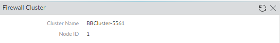
- View NGFW cluster information for an individual firewall on its Dashboard.
- Log on to an individual PA-7500 Series firewall (not Panorama).
- Select Dashboard and for Widgets, select to view the Firewall Cluster card, which displays the Cluster Name and Node ID.
- View NGFW Cluster Summary and Monitoring information and health for the cluster.