NGFW Clusters
Table of Contents
NGFW Clusters
NGFW clustering concepts for PA-7500 Series firewalls.
| Where Can I Use This? | What Do I Need? |
|---|---|
|
One of the following:
|
Learn about NGFW clustering before creating a cluster:
- Benefits and Structure of an NGFW Cluster
- Inter-Firewall Links (IFLs)
- MACsec(PAN-OS 11.1.5 and later releases)
- MC-LAGs, Orphan Ports, and Orphan LAGs
- Node States Determine the Cluster State
- System Faults
- Role of the Leader Node
- Multiple Virtual Systems in an NGFW Cluster(PAN-OS 11.1.7 and later releases)
- Layer 7 Support and Graceful Failover
Benefits and Structure of an NGFW Cluster
Before describing an NGFW cluster, let's review the two legacy HA modes:
- Active/passive (A/P): One firewall actively manages traffic while the other is synchronized to the first firewall (in configuration and states) and is ready to transition to the active state if a failure occurs.
- Active/active (A/A): Both firewalls in the pair are active, process traffic, and work synchronously to handle session setup and session ownership. Both firewalls individually maintain session tables and synchronize to each other. The two firewalls support two separate routing domains.
For the PA-7500 Series firewalls in an NGFW cluster, the control planes (management
planes) of the two firewalls are in active/passive mode where the passive firewall
is fully synchronized to the active firewall in configuration and states.
Additionally, each PA-7500 Series firewall has a maximum of seven data processing
cards (DPC); each DPC has six data planes. The data planes of the two firewalls are
in active/active mode where the firewall with the active management plane
incorporates its own interfaces with all of the interfaces of the passive chassis.
All of the interfaces of both chassis are representable and controllable on a
single, centralized chassis, which is the leader or
leader node
. One node is elected the leader; the other
firewall is a nonleader node. In an NGFW cluster, the firewalls are logically merged
into one logical firewall from the control plane and management perspective. They
have a single routing domain. The NGFW cluster replaces legacy HA pairs and legacy
HA clustering, which are not available on PA-7500 Series firewalls (whether in an
NGFW cluster or not).Use Panorama to configure the PA-7500 Series firewalls for an NGFW cluster. The first
node you assign to the cluster automatically becomes Node 1. After you assign a node
to a cluster, you can't configure the node locally, but must use Panorama. Place all
PA-7500 Series firewalls in a cluster in the same template stack.
NGFW cluster nodes must have the Advanced Routing Engine enabled; they don't support
the legacy routing engine.
Unlike interfaces outside of an NGFW cluster, interfaces on firewalls in a cluster
include the Node ID at the beginning of the interface name. For example,
node1:ethernet2/1 or node2:ethernet1/19.
NGFW clustering is independent of legacy HA pairs and legacy HA clusters. NGFW
clustering is the only HA or clustering solution available on PA-7500 Series
firewalls. However, the firewalls in the NGFW cluster use the Group ID that the
legacy HA uses. The Group ID helps
differentiate MAC addresses when two HA pairs (or an HA pair and an NGFW cluster) in
the same Layer 2 network share MAC addresses. The Group ID is in the same location
within the virtual MAC address for an NGFW firewall node as it is for a legacy HA
firewall node.
Inter-Firewall Links (IFLs)
PA-7500 Series firewalls in an NGFW cluster have a chassis interconnection through
their HSCI interfaces, which function at Layer 2. The firewalls are back-to-back;
HSCI-A ports on each firewall connect to each other, and HSCI-B ports on each
firewall connect to each other. (The firewalls are directly connected to each other;
there can't be a switch or other device between them.) The connections between the
HSCI interfaces are high-bandwidth, inter-firewall links (IFLs) that handle
asymmetric traffic, along with cluster synchronization at a control and dataplane
level. The two IFLs function in active/backup mode. HSCI-A is the default active
link; the active and backup roles are not configurable. If HSCI-A goes down, HSCI-B
becomes the active link.
MACsec
The IFL connection utilizes the HSCI ports on the NGFW exclusively. You can configure
the HSCI-A and HSCI-B for redundancy using an active/backup model.
Beginning with PAN-OS 11.1.5, NGFW clustering allows you to configure Media Access Control Security
(MACsec) on the HSCI interface. MACsec is a standard (802.1AE) that operates at Layer 2. MACsec provides data confidentiality
and integrity between endpoints by adding a security tag and an integrity check
value to each Ethernet frame. It provides confidentiality through encryption of the
data so that only endpoints with the correct encryption key can access the data.
MACsec provides integrity through a cryptographic mechanism, ensuring that no one
has tampered with data in transit. MACsec also provides authentication by ensuring
that only known endpoints can communicate on the Ethernet segment.
You can configure MACsec for the HSCI-A and HSCI-B ports (the active and backup
ports) to protect the Layer 2 connections between the cluster peers. MACsec is
disabled by default; it requires configuration to enable it. (Once enabled, you can
remove the configuration items to disable MACsec.) MACsec runs over each HSCI port.
The firewalls are connected back-to-back, therefore MACsec can establish a tunnel
between the two firewalls. (The firewalls are directly connected to each other;
there can't be a switch or other device between them.) MACsec has an associated
pre-shared key (PSK) that must match on the two HSCI-A ports, and a PSK that must
match on the two HSCI-B ports. Each session confirms that the PSKs match.
On the Communications tab, configuring MACsec involves a field and two profiles for
each node: Key Server Priority (a ranged integer),
Crypto Profile (a drop-down for profiles), and
Pre-Shared Key Profile (a drop-down for profiles).
MC-LAGs, Orphan Ports, and Orphan LAGs
The NGFW cluster supports an MC-LAG, which is a type of LAG. Recall that a LAG (also
known as an aggregated Ethernet (AE) link or aggregate interface group) is a group of
links that appear as one link to provide link redundancy. Links in a LAG that
connect to endpoints on multiple chassis are configured as part of an MC-LAG. The
multiple chassis appear to be a single firewall, providing node redundancy for Layer
3 and virtual wire interfaces only. (Layer 2 does not support MC-LAGs.)
An MC-LAG is an AE interface group that has members spread across both firewalls
(also referred to as nodes or chassis). The illustration below represents different
MC-LAG scenarios. MC-LAGs are controlled by a single control plane and seen as a
single system with a backup management plane. MC-LAG supports redundancy in the
event of link failure, card failure, or chassis failure. Each MC-LAG supports a
maximum of eight members. A pair of firewalls in an NGFW cluster support a maximum
of 64 AE interface groups; the AE interface groups support Layer 3 within the
cluster. (You can have an AE interface group using Layer 2 on a single device, but
not an AE interface group using Layer 2 on an MC-LAG in the cluster.)
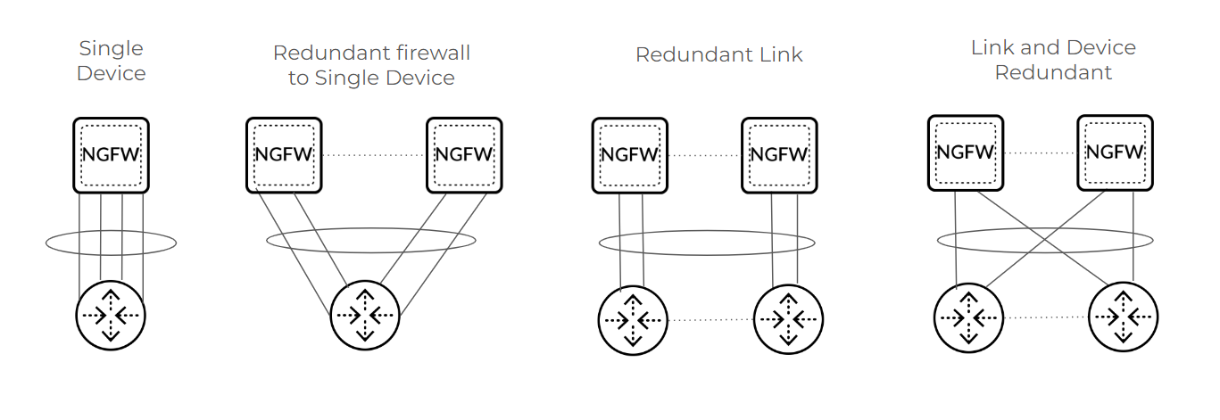
Even a single device scenario can use an MC-LAG, which protects the firewall against
failure, but does not protect against failure of the connected third-party
device.
An orphan port is a single Layer 2, Layer 3, or virtual wire link used for connection
from one node. Instead of using a floating IP address, an orphan port has its own IP
address. The first packet of a session determines the dataplane that owns that
session flow. Return data take the reverse path over the same hops back to the
source.
An orphan LAG is an AE interface group that has all members originating or
terminating on a single firewall (similar to a standalone AE interface group). The
single device in the graphic illustrates an example of an orphan LAG. Firewalls
supported orphan ports and orphan LAGs prior to the introduction of NGFW
clustering.
Aggregate Ethernet local bias is a behavior where traffic forwarding prefers a local
member over remote ports. Because an MC-LAG has members on both nodes, local bias
enforces traffic egress from the local node, instead of forwarding traffic over an
HSCI link to the remote node. (The typical behavior of a LAG is to hash to forward
traffic to any members.)
Node States Determine the Cluster State
The combined node states of the nodes in an NGFW cluster determine the cluster state.
First, let's consider the state of a cluster node, which can be one of these
states:
- UNKNOWN—Clustering isn’t enabled. The node remains in this state until a cluster configuration push from Panorama or a commit enables clustering.
- INIT—Node transitions from UNKNOWN to INIT state after clustering is enabled. Node remains in INIT state until cluster initialization of node is complete. The node transitions to ONLINE state if INIT criteria are met. If INIT criteria fail to be met, the node transitions to ONLINE state after a timeout.
- ONLINE—Node is passing traffic and working as expected.
- DEGRADED—Node transitions to DEGRADED state when a soft fault occurs. DEGRADED state allows Layer 7 continuity for sessions that the DEGRADED state device owns. Traffic links are down in DEGRADED state. The node can transition from DEGRADED to INIT state if all the faults are resolved.
- FAILED—Node transitions to FAILED state when a hard fault occurs. FAILED state has traffic ports down and does not allow Layer 7 continuity. The node can transition from FAILED to INIT state if all the faults are resolved.
- SUSPENDED—Triggered by administrator. Another cause of SUSPENDED state is if a node state flaps to DEGRADED or FAILED state repeatedly; the node is SUSPENDED after six flaps. An administrator can unsuspend the node. SUSPENDED state has traffic ports down and does not allow Layer 7 continuity.
Because the collective states of the nodes in an NGFW cluster determine the cluster
state, the cluster state will be:
- OK—If all nodes are in ONLINE state.
- IMPACTED—If at least one node is in ONLINE state and another node isn't in ONLINE state.
- ERROR—If there isn't a single node in ONLINE state.
The System Monitoring portion of the NGFW cluster configuration allows you to specify
the minimum number of network cards and data processing cards that must be
functional. If the node drops below that minimum, the node state transitions to
DEGRADED or FAILED (whichever you configured).
System Faults
Soft faults and hard faults affect whether the node state is DEGRADED or FAILED. Soft
faults result in a node state of DEGRADED; hard faults result in a node state of
FAILED. Causes of a soft fault are:
- ID Map synchronization has failed.
- IPSec VPN security association (SA) synchronization has failed.
- The system reported an out-of-memory (OOM) fault.
- Chassis does not have minimum capacity and degraded state is configured.
- The cluster node is in degraded state waiting to be suspended.
Causes of a hard fault are:
- Cluster infrastructure service has failed.
- The system reported a disk fault.
- The chassis has no DPC slots up.
- FIB synchronization has failed.
- The chassis does not have minimum capacity and failed state is configured.
- Cluster node configuration is incompatible with other nodes.
- Cluster messaging service has failed.
- Cluster node is avoiding a split brain.
- Cluster node is recovering from a split brain.
Role of the Leader Node
As mentioned, one node of the NGFW cluster is elected the leader node, and the other
node is a nonleader node. The leader and nonleader nodes synchronize the following
system runtime information:
- Management Plane:
- User to Group Mappings
- User to IP Address Mappings
- DHCP Lease (as server)
- Forwarding Information Base (FIB)
- PAN-DB URL Cache
- Content (manual sync)
- PPPoE and PPPoE Lease
- DHCP Client Settings and Lease
- SSL VPN Logged in User List
- Dataplane:
- ARP Table
- Neighbor Discovery (ND) Table
- MAC Table
- IPSec SAs [security associations] (phase 2)
- IPSec Sequence Number (anti-replay)
- Virtual MAC
Upon a leader node failover, the following protocols and functions are
renegotiated:
- BGP
- OSPF
- OSPFv3
- RIP
- PIM
- BFD
- DHCP client
- PPPoE client
- Static route path monitor
Multiple Virtual Systems in an NGFW Cluster
To efficiently use firewalls in a cluster, customers need the cluster to support
multiple Virtual Systems, which are an important capability of an NGFW. Beginning with PAN-OS 11.1.7, an
NGFW cluster supports multiple virtual systems (multi-VSYS). An NGFW node (and
therefore the cluster) supports a maximum of 25 virtual systems. Configure the
PA-7500 Series firewalls in the cluster with the same multi-VSYS support (either
enabled or disabled). The cluster does not support inter-VSYS traffic or shared gateways.
Layer 7 Support and Graceful Failover
In general, NGFW clustering aims to provide parity with HA regarding Layer 7 support.
The following table lists Layer 7 features and whether a standalone PA-7500 Series
firewall supports them, whether NGFW cluster nodes support them, and whether they
support graceful failover.
| Layer 7 Feature | Standalone PA-7500 Series Firewall | NGFW Cluster Node | Graceful Failover |
|---|---|---|---|
| Proxy | |||
| Decryption (Forward Proxy/Inbound Inspection) | Yes | Yes | No |
| Hardware Security Module (HSM) | Yes | Yes | N/A (HSM must be configured per node) |
| Certificate Revocation (CRL/OCSP) | Yes | Yes | Service Route |
| Decryption Port Mirror | Yes | Yes | N/A |
| Network Packet Broker | Yes | Yes, but no redundancy support | No |
| SSH Decryption | Yes | Yes | No |
| GlobalProtect™—IPSec Tunnel | Yes | Yes | No |
| GlobalProtect—SSLVPN Tunnel | Yes | Yes | No |
| Clientless SSLVPN | Yes | No | No |
| LSVPN (Satellite) | Yes | Yes | Yes |
| IDmgr | Yes | Yes | Yes |
| Content Threat Detection (CTD) | |||
| Application-Level Gateway (ALG) | Yes | Yes | No |
| dnsproxy | Yes | Yes | No |
| varrcvr | Yes | Yes | No |
| threat detection | Yes | Yes | No |
| Advance Data Loss Prevention (DLP) | Yes | Yes | No |
| URL Filtering | Yes | Yes | No |
| WIF features | Yes | Yes | No |
| App-ID Cloud Engine (ACE) | Yes | Yes | No |
| User-ID and Configuration | |||
| User Identification | Yes | Yes | Yes |
| Device Identification | Yes | Yes | Yes |
| CUID | Yes | Yes | Yes |
| Device Quarantine | Yes | Yes | Yes |
| Dynamic Address Group (DAG) | Yes | Yes | Yes |
| DUG | Yes | Yes | Yes |
ID Map Sync—Management planes of NGFW cluster nodes individually generate IDs for
various types of objects (such as IP address objects and security profile objects)
in a firewall configuration. These are known as Management Global IDs. Each node
maps its own set of IDs with the set of IDs of the peer cluster node. Some IDs are
used in session flow data. Upon a chassis failover, Layer 4 sessions are marked as
orphaned and sent to the peer chassis for continued processing. During this process,
the IDs in the session flow data are updated to match the set of IDs that the peer's
management plane provided. NGFW cluster nodes must complete their ID map
synchronization before leaving INIT state.
Additionally, Panorama generates a subset of IDs (zone, logical interface, and
virtual router IDs) and pushes them to each cluster node. These are Cluster Global
IDs.
If you need to migrate from a non-PA-7500 Series firewall,
proceed to Migrate to NGFW Clustering.
If you're using a PA-7500 Series firewall, proceed to Configure an NGFW Cluster
and then view the NGFW Cluster Summary and Monitoring information.